User manual
1 Introduction
1.1 Review
Sagitech Video Management System (further Sagitech VMS) is professional software for creation of systems of video surveillance on the basis of IP cameras. Sagitech VMS executes on Microsoft Windows operating systems and supports more than three thousand IP cameras of different makers.
Sagitech VMS allows to carry out the following main tasks:
-
To watch a video in real-time mode from IP cameras, Web-cameras, video servers and IP-video recorders of the system of surveillance using unlimited amount of layouts.
-
To record video data into a distributed archive, using a specified set of conditions and a schedule.
-
To carry out navigation and synchronous/asynchronous monitoring of recorded data from a few cameras simultaneously.
-
To carry out simultaneous work with a set of local or territorially distributed servers from one client place.
-
To carry out intellectual search among data that is recorded in the archive using the following filters: search area, minimal/maximum size of an object, visual characteristics of an object.
-
To use intellectual features that are embedded in IP cameras.
-
To use various parameters of reception of video (different video streams from one camera) for different conditions of monitoring/recording.
-
To carry out control of PTZ-cameras (cameras c with the possibility of pan shot, zoom and a tilt module).
-
To carry out copying and export of images in the playback mode and review of the archive.
-
To convert video data that has been saved in the archive into standard video formats and a quick conversion into the format Sagitech Video.
-
To carry out search and an automatic addition of the found cameras using the protocols of detection, or scanning and analysis of the network.
-
To identify automatically the model of a camera during its configuration.
-
To use digital image scaling of a displayed video (both a recorded one and in real-time mode).
-
To identify a flexible hierarchic system of security on the basis of users and groups with detailed parameters of access to objects of the system.
-
To carry out a simultaneous access to the system of multitude of network users with the possibility of a remote configuration of the system.
-
To carry out surveillance in real-time and reviewing an archive through Web-browser and mobile clients.
-
To receive data from the server Sagitech VMS through HTTP-interface for integration with third-party software and hardware systems.
-
To do tasks (sending SMS, E-mail, an execution of an outside application and etc.) according to a condition (an appearance of a movement, a loss of connection with a camera and etc.).
-
To monitor availability and the condition of a set of servers and cameras that are located on them.
-
To carry out surveillance on several monitors or in a few windows where each monitor (window) can display video data from several cameras.
-
To set up users’ layouts from under an administrator’s account from a remote working place.
-
To carry out controlling cameras that are not displayed on the screen of the operator («Security» mode).
Sagitech VMS is built on the basis of client-server model. It means that it consists of two components.
-
The first component is Sagitech VMS Server. The server is an application that performs all the work of receiving, processing, storing and distribution of information to clients from cameras in a background mode.
-
The second logical component is Sagitech VMS Client. It is an application that allows not only to watch a video from cameras in real-time mode and in an archive-mode, but also to control the work of the server (to set up its parameters).
1.2 Sagitech VMS editions
The Sagitech VMS software is available in 4 editions: Standard, Professional, Enterprise and Complete.
The Standard version is great for creating small and medium-sized video surveillance systems (up to 30 cameras).
The Professional version allows you to create scalable professional systems with an unlimited total number of cameras and flexible capabilities.
The Enterprise edition allows you to combine a set of remote servers into a common domain managed by the main server. There is an opportunity for centralized access to all objects of the unified system through a single access point - both from the point of view of administration, and from the point of view of viewing live/archived video, searching for events, etc. The main server monitors the status of child servers, notifies about the lack of communication with them, manages reservations.
The Sagitech VMS Complete edition combines all the priority functions of Sagitech VMS Enterprise and the most popular video analytics modules. It allows you to optimize and simplify the operation of a video surveillance system for large industrial enterprises, warehouse complexes and federal retail chains and chain restaurants.
Comparative characteristics of Sagitech VMS editions.
| Edition | Sagitech VMS Standard | Sagitech VMS Professional | Sagitech VMS Enterprise |
Sagitech VMS Complete |
|---|---|---|---|---|
| Key parameters | ||||
| Number of cameras on a single server | up to 30 | unlimited | unlimited | unlimited |
| Number of servers in the system | 1 | unlimited | unlimited | unlimited |
| Number of cameras in the system | up to 30 | unlimited | unlimited | unlimited |
| Connecting to multiple servers from a client | - | ✔ | ✔ | ✔ |
| Combining servers into a single system | - | - | ✔ | ✔ |
| Functional parameters | ||||
| Mobile clients | ✔ | ✔ | ✔ | ✔ |
| Web-clients | ✔ | ✔ | ✔ | ✔ |
| Linux client | ✔ | ✔ | ✔ | ✔ |
| Linux server | ✔ | ✔ | ✔ | ✔ |
| Processing audio streams | ✔ | ✔ | ✔ | ✔ |
| Managing PTZ cameras | ✔ | ✔ | ✔ | ✔ |
| External modules | - | ✔ | ✔ | ✔ |
| Alarm monitor | - | ✔ | ✔ | ✔ |
| Screen capture | - | ✔ | ✔ | ✔ |
| Interactive maps | - | ✔ | ✔ | ✔ |
| Camera storage time configuration | - | ✔ | ✔ | ✔ |
| Manual script execution (actions) | - | ✔ | ✔ | ✔ |
| Scheduled tasks | - | ✔ | ✔ | ✔ |
| Active Directory | - | - | ✔ | ✔ |
| Synchronization of configuration objects between servers | - | - | ✔ | ✔ |
| Reservation | - | - | ✔ | ✔ |
| Monitoring the status of servers | - | - | ✔ | ✔ |
| HTTPS-encryption of traffic between server and client | - | - | ✔ | ✔ |
| Shared layouts | - | - | ✔ | ✔ |
| Analytical modules | ||||
| License plate recognition | - | € | € | € |
| People counter | - | € | € | ✔ |
| Face detector | - | € | € | ✔ |
| Tracking | - | € | € | ✔ |
| Smoke detector | - | € | € | ✔ |
| Fire detector | - | € | € | ✔ |
| Sabotage detector | - | € | € | ✔ |
| Loud sound detector | - | € | € | ✔ |
| Abandoned items detector | - | € | € | ✔ |
| Fisheye module | - | € | € | ✔ |
| Heatmap | - | € | € | ✔ |
| POS module | - | € | € | ✔ |
| Monitoring of personnel activity | - | € | € | ✔ |
| Connection an external microphone | - | € | € | ✔ |
| Interactive Dome | - | € | € | ✔ |
| Neural network object detector | - | € | € | ✔ |
| Neural network fire and smoke detector | - | € | € | ✔ |
| Queue detector | - | € | € | Special price |
| Face recognition | - | € | € | Special price |
| PPE control | - | € | € | Special price |
1.3 Sagitech VMS Enterprise features
1.3.1 Review
The Enterprise edition allows you to combine a set of remote servers into a common domain. One server is the main one, it is responsible for changing the configuration. The other servers synchronize copies of the configuration with the main server. The client first tries to establish a direct connection to all servers. If this is not possible, then it requests from the server through which it is connected the proxying of streams from the necessary servers.
The main server monitors the status of the child servers, notifies about the lack of communication with them, and manages the reservation.
1.3.2 Server configuraion
The object tree has been changed in this revision. In the Standard and Professional editions, the "Disks" and "Information" sections are located in the parent branch of objects and contain information for the current server, see the image below.

In the Enterprise edition, the "Servers" section has been added to the object tree. The "Disks" and "Information" sections are located in the parent branch of a particular server.

Icon
 means that the server is main.
1.3.2.1 Working with disks
Disk configuration is performed in the same way as other editions, see point 5.1 Work with disks
1.3.2.2 Recording profiles
The configuration of recording profiles is performed in the same way as other editions, see paragraph 5.2 Recording profiles
1.3.2.3 Setting up cameras
The configuration of the cameras is performed in the same way as other editions, see point 5.3 Setting up cameras
In the Enterprise edition, all cameras are displayed in the camera list, i.e. from secondary servers, and the name of the server to which the device is connected is indicated in the table.

1.3.2.3 Setting up users
Configuration of users and user groups is performed in the same way as other editions, see paragraph 5.5.2 Setting up users
In the Enterprise edition, importing users from Active Directory is available. In the "Users" section in the object tree, click the "Add from Active Directory" button.

Log in to the domain.

Select the users to import and click OK.
1.3.2.4 Event processing
Scripts are configured in the same way as other versions, see paragraph 5.6 Event processing(scripts)
1.3.2.5 System status information
The "Information" section of the configurator allows you to get information about the functioning of a specific server, see the point 5.8 Information about system condition
1.3.2.6 Schedules
Scheduled tasks are configured in the same way as other editions, see the point 5.10 Schedules
1.3.3 Shared layouts
This section allows you to create shared layouts for a set of users.
Specify the name of the layout and set up the cameras.

Shared layouts are marked with a white dot and are always at the end of
the layout list.

You can move the cameras in them, but the changes will not be saved and when you log in to the layout again, it will load without accepting the changes. If the layout does not contain cameras that the client is allowed to watch, then the client will not see this layout. If there is at least one camera available to the client, then the layout will load with this camera(s). The play lists can contain both user layouts and shared layouts.
1.3.4 HTTPS- encrypting the traffic between the server and the client
To connect with HTTPS, use the information in the section 3.6.4 Connecting to the server with HTTPS protocol
1.3.5 Sending messages to Telegram
In the user settings, go to the "Advanced" tab and click the "Configure" button.

Enable integration with Telegram. Click OK.

Save the changes.
Click on the generated link. And click "Start". Upon successful registration, you will see the message "You have successfully registered".
Scripts are configured in the same way as other versions, see paragraph 5.6 Event processing(scripts)
Select the "Send message to messenger" action.

Select the user and the message text.

2 Installation
2.1 Windows
In order to install the system it is necessary to have an installation disk with the system software Sagitech Video Management System, or to download it from the official website of the product from the section «Download» (https:// sagitech.pro/download).
In order to start installation of the product it is necessary to start the file SagitechVMSSetup.exe. After initiation of the installation wizard, a welcome window will appear (Fig.2.1). In order to continue the installation it is necessary to click the button «Next».
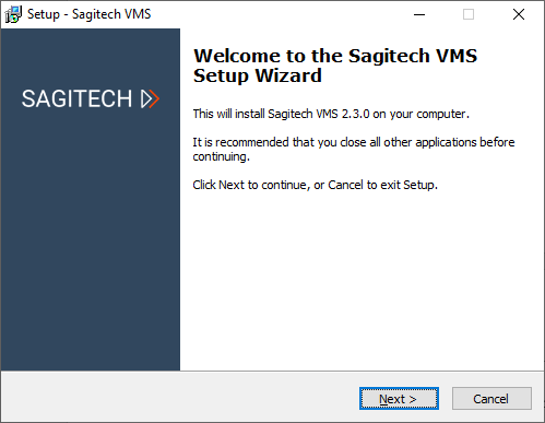
Fig. 2.1 System installation wizard
In order to continue installation, you have to read and accept the terms of the license agreement. Without accepting the terms of the license agreement it is impossible to continue the installation of the product. After reading and accepting the terms of the license agreement, it is necessary to click the button «Next».

Fig. 2.2 The window for choosing a folder for installation of the system
After this, it is necessary to choose a folder for installation of the system, as it is shown in Fig. 2.2, then click «Next».

Fig. 2.3 The window for choosing the components for installation
After this, the wizard window will appear for choosing components for installation (Fig. 2.3). In this window you can choose a type of installation - to install both components (Client and Server), or only the client application. After choosing the necessary configuration it is necessary to click the button «Next».
After that, a window will appear where you can specify the folder of the menu «Start» that will contain the elements for starting the software product (Fig. 2.4), after making a choice it is necessary to press the button «Next».

Fig. 2.4 The window for choosing a folder that will contain the elements of the system in the «Start» folder
In the window that appears after this, it is necessary to choose specific file shortcuts which should be displayed in the user desktop (Fig. 2.5). In order to continue the work of the installation wizard, it is necessary to click the button «Next»

Fig. 2.5 The window for installation of the file shortcuts
The window of readiness for installation (Fig. 2.6), shows the finish of the process of gathering all necessary data and the readiness of the wizard to take all the necessary actions for the installation of the system Sagitech VMS. Check the parameters that you entered earlier and click the button «Install».

Fig. 2.6 The window of readiness for installation
The wizard window will appear for finishing the setup after a successful installation of the system (Fig. 2.7). If you install both the client and the server components, then the option «Start the server setup wizard» will be available for choosing in this window. We advise you to leave this option active - then after clicking the «Finish» button a wizard will be started which will help you to perform the initial setup of the server. Take into account that the server will be started only after going through all the stages of the work of the Server setup wizard. So if you switch off this option, then you will need to start the server manually from the «Start» menu.

Fig. 2.7 The finish of the work of the system installation wizard
2.2 Linux
To install the system, you need a product distribution kit, which is located on the official website of the product https://sagitech.pro/download/.
2.2.1 Ubuntu
To start installing the product, you need to launch the terminal window (Ctrl + T).
2.2.1.1 Installing the server
It is recommended to update the package information before installation:
sudo apt update
You can install the current version of the distribution directly from the terminal using the script:
sudo su -c "bash \<(wget -O - https://sagitech.pro/linux/install/sagitech-vms-server-ubuntu.sh)"

If you have already downloaded the file to your PC in another way, then go to the directory with the file (for example: cd Desktop) and run the installer with the command:
sudo apt install ./sagitech-vms-server.deb
Note
Please note that the name of the installer file may differ from the example above.
To continue the installation, you must enter the password to obtain superuser rights. The system will check the dependencies, identify the packages needed for installation and ask for confirmation. Press Enter.
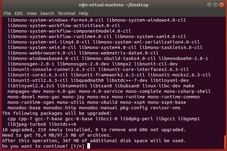
After downloading the necessary packages, the installer will ask for a password for Firebird. Type "masterkey" (in small letters, without quotes) and press Enter. The packages will be installed into the system. If successful, there should be no error messages.
The application files are installed in the directory /opt/sagitech-vms.
The server is not running after installation. Before starting the server, you must activate the server (see point 3.2.2).
Manual control of server start/stop is possible with console commands:
Start:
sudo /etc/init.d/sagitech-vms start or systemctl start sagitech-vms
Stop:
sudo /etc/init.d/sagitech-vms stop or systemctl stop sagitech-vms
2.2.1.2 Installing the client
It is recommended to update the package information before installation:
sudo apt update
You can install the current version of the distribution directly from the terminal using the script:
sudo su -c "bash \<(wget -O - https://sagitech.pro/linux/install/sagitech-vms-client-ubuntu.sh)"
If you have already downloaded the file to your PC in another way, then go to the directory with the file (for example: cd Desktop) and run the installer with the command:
sudo apt install ./sagitech-vms-client.deb
Note
Please note that the name of the installer file may differ from the example above.
The application files are installed in the directory /opt/sagitech-vms-сlient.
To launch the application, click on the application shortcut in the "All" menu section.
3 Server
3.1 Overview
Sagitech VMS system server is a key component of the system that carries out all the responsibilities of receiving videos from cameras, keeping an archive, distribution of video and other data to a user. Server is the only component of the system that needs a license for work in a full functional mode. Depending on a necessity, it can be started either as an application or as Windows service.
The following set of executable files will be installed to your computer when you choose the «Server» component during the installation.
Sagitech VMS server setup wizard
This utility allows to set up the main parameters of the server and to activate your software. By default, this application is launched when the process of installation of Sagitech VMS is finished.
Sagitech VMS Event log
This application allows to see the list of events that happened on the server.
Sagitech VMS Server (application mode)
This application performs the role of the server that will be connected to by clients. It is used when choosing the method of starting as an application.
Sagitech VMS Server (service mode)
This application performs the role of a server if it is necessary to start it in the mode of system service.
The first three of the above listed applications are available for starting through the «Start» menu. The last, the fourth one, will start automatically and it will be available for setting up through snap-in «Services» of the system Microsoft Windows (by default the server starts in the application mode, in order to switch to the service mode it is necessary to perform setting up with the help of Server Setup Wizard).
In more detail the functionality of all the four utilities will be addressed in the corresponding sections.
Pay attention that administrator's rights are necessary for functioning of the server part of the Sagitech VMS system. It is related to the necessity of access to the register, the database of the settings of the server and disks for keeping an archive. If the server starts automatically when a user enters the system (application mode) then it is necessary to turn off Account Control – UAC (otherwise, the server will demand switching to the administrator's mode at every start). No additional setting up will be needed when in system service mode
3.2 Server setup wizard
3.2.1 Windows
If you have chosen the option «Start server setup wizard» in the window of finishing the installation of the Sagitech VMS system then this utility will be started automatically after the installation of the system. You will also be able to start it at any moment from the «Start» menu (Fig. 3.2.1).

Fig. 3.2.1 Starting server setup wizard from the «Start» menu
This utility will allow to activate your Sagitech VMS copy and also to set up the method of starting the server and to specify the password of the system administrator.
A welcome window will appear after starting Server setup wizard (Fig. 3.2.2). Press the «Start» button in order to start the process of configuration.

Fig. 3.2.2 Welcome window
The second window of the wizard will offer to you to choose the scheme of activation of the product (Fig.3.2.3). If you have purchased the Sagitech VMS system and, accordingly, have the serial number, then choose the option «Activate application», after which you will be able to register your Sagitech VMS copy. Otherwise, if you are interested in the functionality of the system and you have installed it with the purpose of becoming acquainted with it, then choose the «Use trial version» option. The trial version has some restrictions that will be addressed later. Press «Next» in order to continue the work of the wizard.

Fig. 3.2.3 Choosing the way of activation of the product
The window of activation appears when choosing the «Activate application» option (Fig. 3.2.4). If you have chosen «Use trial version», then there will be a transition to the window of specification of the system administrator's password.

In order to activate the product online you need a serial number which is supplied together with the disk of installation of the Sagitech Video Management System, or it is mailed when buying online.

In order to activate the product offline you need a serial number and code of activation which should be received from a representative of the customer service of the system. The activation code is given to a customer after he submits the serial number of the product and the equipment code which is automatically generated when entering the product serial number.

Fig. 3.2.4 Product activation window
The window of finishing the activation will appear after inputting the activation code and pressing the «Next» button.
Check the data about the amount of cameras supported by your license and press the «Next» button.
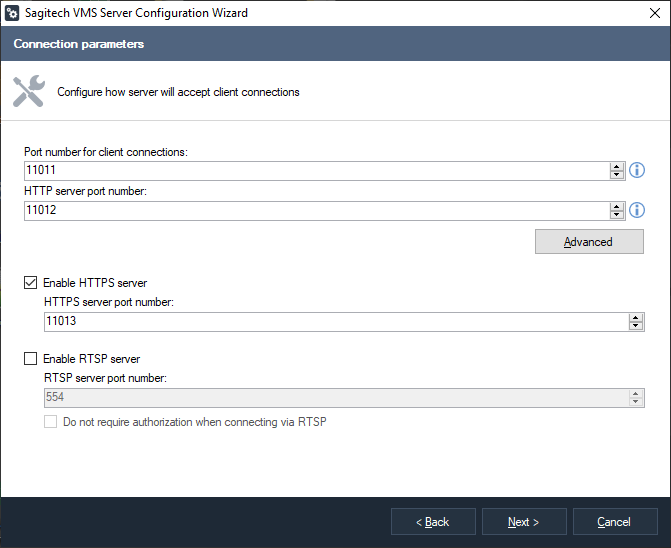
In the next window of the wizard you can set up the numbers of the ports that will be used for connection to the server (Fig. 3.2.6). Three kinds of connection are supported:
-
connection through Sagitech VMS Client (port 11011 and port 11012);
-
Web-browser and mobile client connections (port 11012);
-
secure Web-browser connections (port 11013).
Pay attention that when there is a change of the port number for receiving client connections it will be necessary to set this port number in the Sagitech VMS Client application in the server name line (example: «server1:11014»). Press «Advanced» button if you need to configure web server transcoding parameters. Transcoding applies when video data is being sent to mobile and web clients.
The "Enable RTSP server" flag allows you to receive video streams in real time and an archive from the Sagitech VMS Server.
 |
 |
|---|---|
Fig. 3.2.6 Setting up port numbers and transcoding parameters
After clicking the «Next» button, a window will appear in the screen, in which you can set up a password for the administrator's account (Fig. 3.2.7). The administrator has the «admin» name and his password is blank by default. Set up a new password in the field of the same name and repeat it in the «Password confirmation» field.

Fig. 3.2.7 Setting up an administrator's account
After clicking the «Next» button a window will appear where you can choose the method of the start of the system (Fig. 3.2.8). The server must be started in order to enable it to carry out its functions. If you need the system occasionally then you can start it manually through the «Start» menu. Choose the «Manual execution» option for this. If you need the application to start automatically for carrying out its functionality in a constant mode then you need to choose from the rest of the three options.
When the «Start automatically for the current user» method is chosen the server will start after a user inputs a password when he enters the Windows system. If you have chosen the «Start automatically for any user» option, then the start will happen for any user when he enters the system.

Fig. 3.2.8 Choosing the method of the system start
The last method is optimal for setting up a day and night surveillance. It allows the Sagitech VMS server to start immediately after booting the Windows system, even if you have not input a password for entering the system yet. The setup wizard will not allow you to choose this start method if you choose a trial version.
After pressing the «Next» button a window will appear that will precede the server setup start.
Click «Next» that the wizard might carry out all the server setup operations in accordance to the data that you have entered. After this the window appears, which informs you that the initial system setup has finished successfully and for correct work it offers to start (or to restart, if it was started earlier) the server. Restarting is a necessary condition that enables the server to accept the entered changes.
3.2.2 Linux
3.2.2.1 Ubuntu
To activate the program, click on the application menu button at the
bottom left of the screen
( ),
select the “All” category and launch the "Sagitech Wizard" application.
The application will require authorization under the superuser. Next,
activate and configure the necessary parameters. Upon completion of the
wizard, the server will be started. Activation is performed by analogy
with clause 3.2.1.
),
select the “All” category and launch the "Sagitech Wizard" application.
The application will require authorization under the superuser. Next,
activate and configure the necessary parameters. Upon completion of the
wizard, the server will be started. Activation is performed by analogy
with clause 3.2.1.
If you are using Linux without a GUI interface, activation is performed using the following commands:
-
activate: display activation information
-
activate [SerialNumber]: generate the hardware code
-
activate [SerialNumber] [ActivationCode]: activate the program using the specified serial number and activation code.
Usage example: sudo /opt/sagitech-vms/RSWizard.sh -activate [SerialNumber], where [SerialNumber] - your serial number.
Manual control of the start/stop of the application is possible with console commands:
Start:
sudo /etc/init.d/sagitech-vms start or systemctl start sagitech-vms
Stop:
sudo /etc/init.d/sagitech-vms stop or systemctl stop sagitech-vms
3.3 The work of the server in the application mode
If during the execution of the Server setup wizard you have chosen the start in the application mode, then during the work of the server its icon will be put in the task bar (System Tray):
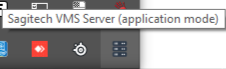
Fig. 3.3.1 The server is started in the application mode
Furthermore, if you have chosen the «Start server» option in the last window of the wizard then the server will start automatically. When started manually it is available through the «Start» menu:

Fig. 3.3.2 Starting the server from the Windows «Start» menu
In the case of choosing the product tryout then when it starts you will see an information window with information about restrictions imposed by the absence of the license (Fig. 3.3.3). If your version is registered then this window will not be displayed.
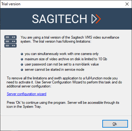
Fig. 3.3.3 Restrictions imposed by the trial version of the program
After clicking the «Ok» button the server will start its work. Also you can click the «Server configuration wizard» hyperlink for a fast start of the wizard with the goal of changing registration data.
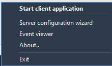
When clicking with the right mouse button on the icon of the system server, a right-click menu will appear in the notification area which offers the following options for action:
-
to start the client application;
-
to start the Server setup wizard;
-
to start The Server event logs;
-
to get information about the program;
-
to finish the work of the server.
When clicking twice with the left mouse button on the server icon the Sagitech VMS system client will be started.
You can find out the information about your license in the window of information about the program.

Fig. 3.3.4 Information about the system server
In a period of time only one copy of the Sagitech VMS server can be started in the system. If you receive the «The application has already started» message when starting, and in the notification area the server icon is absent then it means that the server is started in the service mode.
3.4 The work of the server in the service mode
If during an execution of the Server setup wizard you have chosen the start method «Start automatically when the computer starts», then the Sagitech VMS server will start in the form of the Windows service. The server execution can be controlled through the «Services» functionality of the Windows control panel (Fig. 3.4.1).
Also, if you start the Sagitech VMS Server application in this mode, the icon will not be displayed in the task bar, but the quick service control window will appear (Fig. 3.4.2).
Fig. 3.4.1 Service control through the “Services” snap-in |
Fig. 3.4.2 Service control through the application |
|---|


3.5 Server event log
The Server event log contains a list of system events (Fig. 3.5.1). This log allows to trace appearance of execution errors, for example, such as loss of connection with the camera.
When the event log is started, the screen, by default, displays the events that happened on the server during the last 24 hours. You can choose events for a different period of time by using the «Search events» button. Also this button allows to filter according to different parameters. The «Refresh» button allows to refresh the contents of the event log.
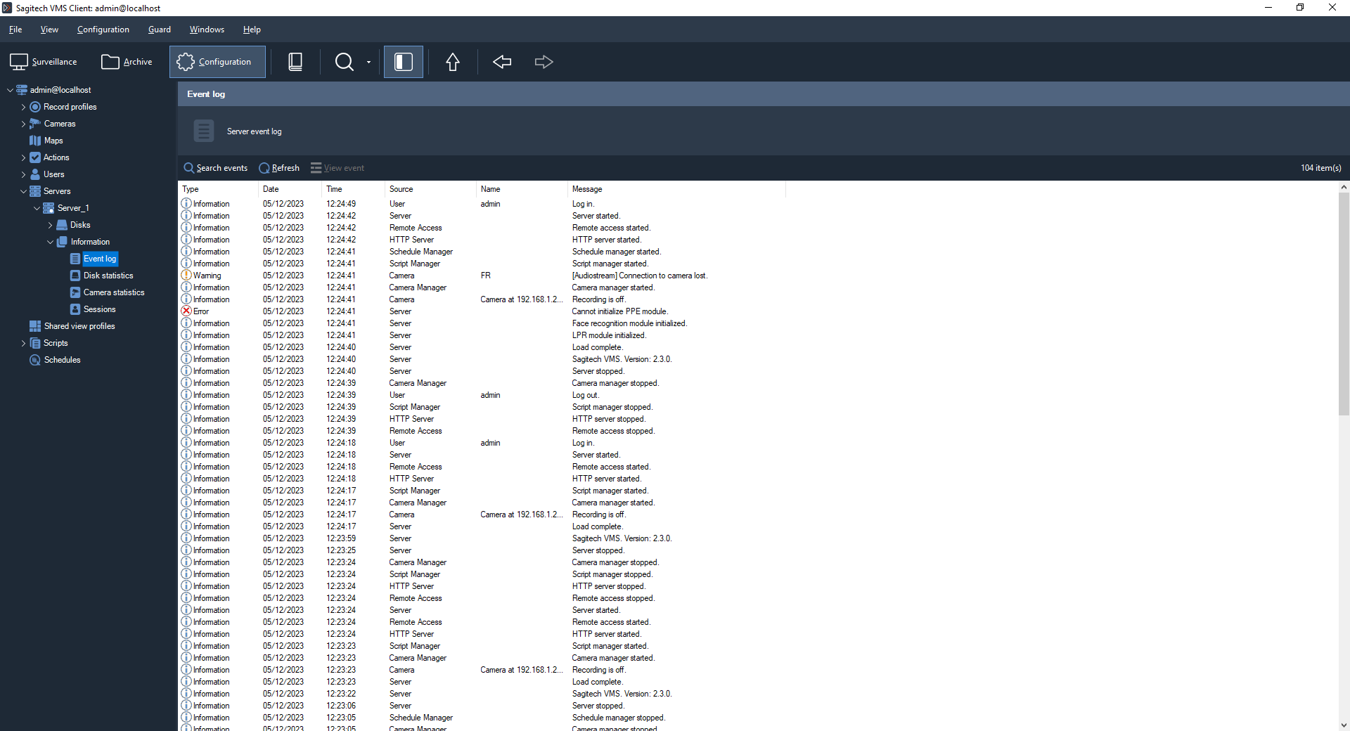
Fig. 3.5.1 The event log of the system server
You can see the properties of an event in greater detail by pressing the «View event» button (Fig. 3.5.2).

Fig. 3.5.2 Event properties
3.6 Connecting to the server with HTTPS protocol
3.6.1 Enabling the HTTPS Sagitech VMS server
Run the Sagitech VMS Server Settings Wizard, by default C:\Program Files\Sagitech VMS\RSWizard.exe . In the window that opens, you will see information about the current license. In the next step, enable the HTTPS server and change the port if necessary.
Complete the configuration and restart the server. If you have done everything correctly, then you will see a message in the server event log that the HTTP server has been successfully started. By default, a self-signed certificate is used. This certificate has the following disadvantages:
-
Problem with browser support
-
Cerificate substitution within the network.
Additional settings will be required to use a third-party certificate.
3.6.2 Installing a third-party certificate
Users of the web application will need to confirm an insecure connection every time; which, in turn, may cause distrust on the part of users.
To install the certificate on your computer, you need to run the "Certificate Import Wizard" (open the format file.pfx) and set the flag to "Local computer".
-
Specify the path to the file.
-
Enter the password and click Next.
-
Place your certificate in the "Trusted Root Certification Authorities" repository.
-
Complete the installation.
-
To verify the certificate, run the Snap-in Console, and type the command mmc in the Start menu.
-
Add a snap-in: File-Add or remove a snap-in. In the Available Snap-ins tree, select Certificates and click Add. In the "Certificate Manager Snap-in" window that appears, select "Computer Account" and complete the configuration.
-
Click OK. In the object tree, you will see the item "Certificates" (local computer). It is necessary to expand the drop-down list of this element and select "Trusted root Certification Authorities". You should see your certificate in this list.
3.6.3 Binding the certificate to the Sagitech VMS configuration
In the list of certificates (see point 3.6.2), select your certificate and press LMB 2 times. In the window that appears, go to the "Composition" tab and select the "Fingerprint" field. The value of this field must be copied.
The next step is to open the file C:\Program Files\Sagitech VMS\config\Sagitech.config (using the Notepad program) and edit the line:
<add key="HttpsCertificate" value="" />
The previously copied fingerprint identifier must be inserted into the value parameter:
<add key="HttpsCertificate" value="12fdg123fl125643fdjgnwu" />
Save the changes.
3.6.4 Connecting to the server with HTTPS protocol

To connect via HTTPS, enable the data encryption flag in the session settings.
3.7 Getting the rtsp stream of the Sagitech server

The "Enable RTSP server" flag allows you to receive video streams in real time and an archive from the Sagitech VMS Server.
3.7.1 Real-time stream
RTSP url:
rtsp://127.0.0.1:554/live/70ee9e47-a48a-4ca9-96a7-7e8b46399bd7?stream=0
Where:
-
70ee9e47-a48a-4ca9-96a7-7e8b46399bd7 - camera ID (taken from the camera settings window in the software, from the Advanced tab)
-
stream=0 - stream index (0-main, 1-sub).
3.672 Archive stream
RTSP url:
rtsp://127.0.0.1:554/archive/70ee9e47-a48a-4ca9-96a7-7e8b46399bd7?from=2019-05-06T00:00:00&to=2019-05-06T00:15:00
Where:
-
70ee9e47-a48a-4ca9-96a7-7e8b46399bd7 - camera ID (can be taken from the Advanced tab of the camera settings window)
-
from – the start time of the playback
-
to – end time of playback (optional)
4 Client: general information
4.1 Overview
Sagitech VMS Client is the main instrument of interaction with the servers of Sagitech VMS video surveillance system (both with local ones and remote ones). It allows to carry out both administrative tasks (editing the list of cameras, setting up security parameters etc.), and client tasks – watching a video in real-time mode and reviewing an archive.
Sagitech VMS Client can be installed both with a server and separately form it on any computer where there must be access to a video surveillance server. In such a way, you can set up your servers or your user profile from any computer where this software is installed.
4.2 Start
You can start the client application from the «Start» menu (Start->All programs-> Sagitech Video Management System -> Sagitech VMS Client) (Fig. 4.2.1), or by clicking the server icon in the system tray (when working in the application mode) and by choosing the option «Start client application» (Fig. 4.2.2).
Fig. 4.2.1. Starting the system client from «Start» menu |
Fig. 4.2.2 Starting the system client from the Windows system tray |

If necessary, when starting the application execution file, you can use the parameters specified in the table 4.2.1:
Table 4.2.1. Additional parameters when starting an executable file of the system client.
| Parameter | Description |
| /profile:ProfileName | Specifying the user profile which will be chosen when the system is started. |
| /session:SessionName | Specifying the session which will be chosen. |
Example
rsclient.exe /profile:by default /session:admin@localhost
This functionality can be used for the creation of a token for a specific session and a profile when there are several profiles of user settings and several sessions. For example, you can create two tokens for simultaneous starting of two copies of the program on different monitors with connections to two different Sagitech VMS servers.
4.3 Connecting to a server
When starting Sagitech VMS Client, you will be offered to log in the server. When this happens a login window will appear (Fig. 4.3.1). In this window it is necessary to specify the server address that is connected to, a user name and a password. By default only one admin user is present in the system with a blank password:

Fig. 4.3.1 The window of authentication on the Sagitech VMS server
The combination of a server address and a user name will be automatically saved in the form of Username@Serveraddress after connecting to the server. This combination is called session. Previous sessions are accessible for choice in a drop-down list with the same name.
Check «Remember password» for automatic saving of the password together with the other parameters of a session, check «Connect automatically» in order to enable automatic connection when starting the program without waiting for actions of a user.

Fig. 4.3.2 Choosing the user setting profile
The «Settings» button allows to create, to change, or to delete the user setting profiles (Fig. 4.3.2). The profile allows to group the application parameters (the session list, the location of the application main window on the monitor etc.). For a system with several servers the profiles and the command prompt parameters provide a way for automation of the start of several program copies that connect to different Sagitech VMS servers on several monitors simultaneously.
Click the «Ok» button in the window of entering the system after inputting necessary information. If all the parameters have been entered in the right way, you will be connected to the server, in the case of an error a dialog window will be displayed with information about the error (Fig. 4.3.3). For example, in the figure below a user has entered his name and his password in the wrong way. Address the system administrator if you cannot eliminate the error.
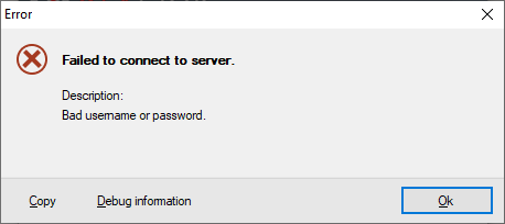
Fig.4.3.3 Server connection error
4.4 Connecting several servers simultaneously
Sessions can be united as a group. A group allows to set up simultaneous connection to several servers and to work with them simultaneously from one Sagitech VMS Client application. In order to create a group, click the button «..» on the right from the list of choosing a session in the connection window (Fig. 4.3.1). When this happens a window will appear on the screen that will allow to edit the list of sessions and groups manually (Fig. 4.4.1).

Fig. 4.4.1 Window for editing of sessions
Click «Add -> Group» for the creation of a new group of sessions (Fig. 4.4.2). You can safeguard the group with a password, and then when connecting to a group you will need to input the saved password in the authentication window.

Fig. 4.4.2 Window of adding a group of sessions
When choosing a group in the window of editing sessions and clicking «Add -> Session», the newly created session will get just into the specified group (if before adding you choose the category «[Sessions]», then a ungrouped session will be created). Sessions can also be moved to a group by a usual drag-and-drop (Drag&Drop). When adding a session to a group you will need to enter the server address, a user name and a password. Also you can specify the server name – description-line, under which the server will be displayed in dialog windows of Sagitech VMS Client (Fig. 4.4.3).

Fig. 4.4.3 Window of adding a session to a group
4.5 The main window and work modes
The main window of the Sagitech VMS Client application will appear on the screen after authentication in the system (Fig. 4.5.1):
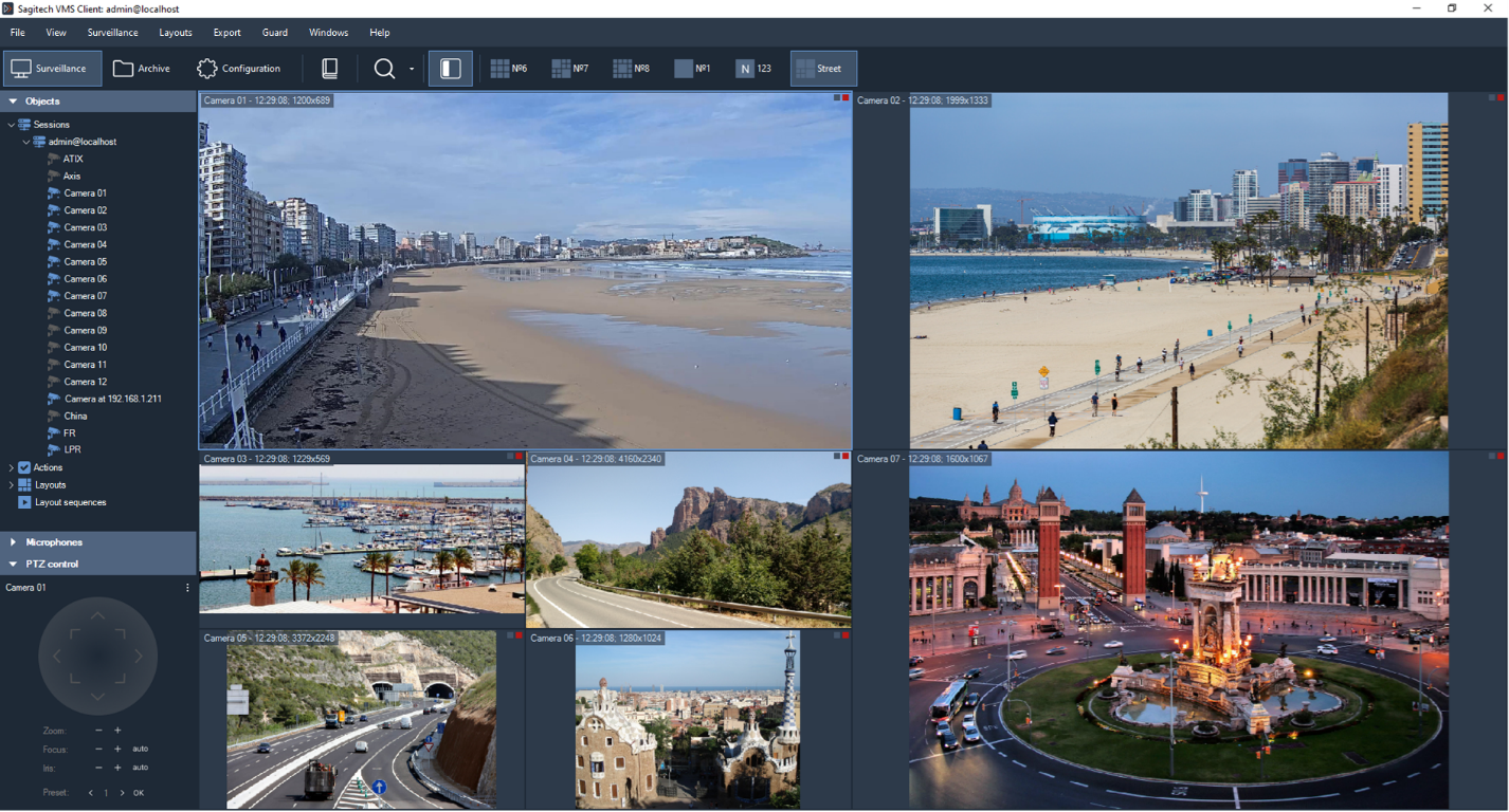
Fig. 4.5.1 The main window in the mode of surveillance
The application menu and the toolbar are located in the upper part of the main window. They serve as the main instruments of interaction with the program. There are constant and context control elements that are located on them. Context elements depend on the mode (context), in which you are currently. The constant elements are accessible from any mode.
It is possible to work with the program in the following modes:
-
Surveillance. It allows to view real time video streams simultaneously from several cameras.
-
Archive. It allows to watch a recorded video.
-
Configuration. It allows to configure the parameters of the surveillance server.
You can choose the necessary mode through the View menu (Fig. 4.5.2), or through buttons with the same names on the toolbar.
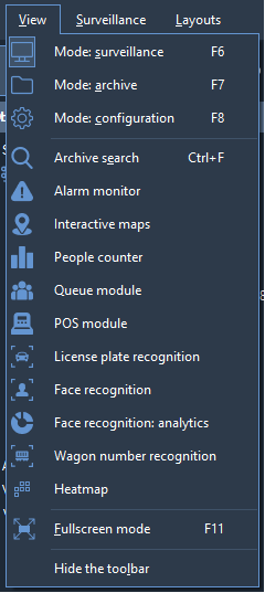
Fig. 4.5.2 .The functionality of the View menu
Context-free control elements are located in the menu File, View, Guard, Windows and Help. The most used ones of them are located in the left part of the toolbar. The purpose of these elements is presented using the example of the menu in the table 4.5.1:
Table 4.5.1 The functional purpose of the menu elements of the client
| Menu | Menu option (control element) |
Purpose |
| File | Settings | Activation of the window of application settings. |
| Logoff | To finish the current session and to use the connection window for logging in as a different user. | |
| Exit | To exit the application | |
| View | Mode: surveillance | Switching to the mode of surveillance. |
| Mode: archive | Switching to the mode of archive browsing. | |
| Mode: configuration | Switching to the mode of server configuration. | |
| Archive search | Switching to the mode of search in the archive | |
| Full-screen mode | Switching to the full-screen mode and vice versa | |
| Hide the toolbar | It hides the toolbar. | |
| Guard | Alarm log | It displays or hides the alarm log |
| Guard mode | It displays the window of activation and setup of the guard mode | |
| Windows | To add a window | It adds an additional window of surveillance |
| To close all windows | It closes all additional windows of surveillance | |
| Help | User guide | To show this user guide. |
| Advice about using | To show the window with advice about the use of the program. | |
| About the program | To show the information about the program |
The administrator might restrict access to some of these control elements and because of this they will be inaccessible. For example, it is possible to disable the ability of viewing the archive by some users. Also it makes sense to allow only a limited group of people to have access to the configuration mode. In more detail the access privileges will be addressed in the description of editing of users and groups.
A tool panel is located in the left part of the main window of the program. It provides quick access to the data structures (lists of cameras, layouts, records etc.) and additional control elements. The contents of the panel are context-dependent and will be addressed for each application mode separately.
5 Client: configuration mode
This mode contains all the functionality that is necessary for setting up the surveillance server and also for monitoring its condition. When switching to the configuration mode you will discover the section tree in the left part of the window and the contents of the chosen element of the section tree in the right part (Fig. 5.1).

Fig. 5.1 Setting up the system configuration
The section tree consists of server-elements, each of which, in its turn, consists of several groups, each of which contains elements of one type (table 5.1):
Table 5.1 The functional purpose of the groups of the configuration mode.
| Group | Description |
| Disks | It contains the list of disks of the surveillance server. It allows to set up the use of disk space for record storage. |
| Recording profiles | It contains the list of recording profiles. It allows to specify the unified recording profiles which can later be applied to a set of cameras. |
| Cameras | It contains a list of cameras that are registered on the server. |
| Users | It contains the list of users and their groups. It allows to specify the parameters of security. |
| Scripts | It contains a list of scripts - objects that allow to specify the responsiveness of the system to events. |
| Information | It contains the information about functioning of the system. It allows to view the event log and statistics. |
5.1 Work with disks
In the «Disks» section of the configurator you can specify the devices which will be used for storing video information. A list of disk devices of your server will appear in the right part of the program window when going to this section (Fig. 5.1.1).

Fig. 5.1.1 Setting up system disks
In order to choose the necessary disk for recording it is necessary to check «Use» (by default the entire disk will be used for recording) or to choose a disk and to click «Edit». Then a disk editing window will be displayed (Fig. 5.1.2).

Fig. 5.1.2 Editing the disk parameters
This window allows to specify how a disk will be used for storing the archive. Three options are possible:
-
The disk is not used for storing video data. Choose this option in order to exclude the disk from the list of devices for storing archives. When this happens all the cameras that record to this disk will stop filing until connection of the disk or configuring the parameters of recording of cameras.
-
The disk is entirely used for storing data. Choose the option «Use the entire disk space».
- A limited space of the disk is used for storing the archive. Choose «Use a part of the disk» and specify the necessary capacity in the field «Quota».

Pay attention that you need to provide some free space on the disk for correct recording (the “Minimum free space” field).
The field “Store events and video analytics” enables event data storage on the selected disk.
Choose the necessary disk parameters and click «Ok». Pay attention to the fact that if your Sagitech VMS system is not activated then you will not be able to choose more than 10 GB of disk capacity for storing records.
If necessary you can set up the parameters of recording for a set of disks at a time. In order to do this, check several disks in the configurator by using the button Ctrl and click «Edit». When this happens the general characteristics of the checked disks will be displayed (Fig. 5.1.3). The fields of the editing window, that correspond to different characteristics, will be blank. If to edit any of the fields and to click the «Ok» button, then the entered changes will be accepted for all chosen disks simultaneously. When using several disks for recording, the recording on them is performed cyclically in order to provide the fastest access to the information.
Fig. 5.1.3 Changing parameters for several disks of the system |
Fig. 5.1.4 The window of adding a network disk |


If necessary you can use network devices/disks for storing the archive. The «Connect» and «Disconnect» buttons allow to control installing such devices into the system as usual disks. After adding a disk (Fig. 1.5.4), it will automatically connect when the server starts independently of the mode of the work of the application. Pay attention that if to connect a network disk through the Windows file explorer, instead of the server configurator, then, when started in the system service mode, the application will not be able to address the network disk.
5.2 Recording profiles
A combination of settings of recording parameters is called a recording profile. Profiles allow to set unified parameters of filing for several cameras simultaneously. It allows to apply and to keep track of changes faster.

Fig. 5.2.1 Setting up record profiles
By default the system already has a set of pre-defined record profiles that is available in the corresponding section of the configurator. An editing window with two tabs will be displayed when adding or editing a recording profile (Fig. 5.2.2).
 |
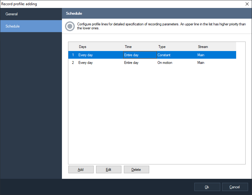 |
Fig. 5.2.2 Adding a new recording profile
In the tab «General» you can set up the basic profile parameters – a unique system name and a description.

Fig. 5.2.3 The parameters of a record profile
The tab «Schedule» allows to set the list of recording parameters (profile lines) that are connected to a time period. For example, in the Fig. 5.2.3 the profile consists of two lines, the first of which specifies that it is necessary to make constant recording during a work day (from 8 to 17 o'clock) by using the main stream of a camera, and the second -to make recording by using an additional stream outside working time with the help of a motion detector.
When analyzing a profile, its lines are browsed from top downward, in other words if you have specified intersectional time periods for two lines then during this intercrossing a line will be used that is higher in the list. In order to move lines use the «Move up» и «Move down» options of the context menu (it is activated by clicking with the right mouse button on the list of the profile lines).
The window of editing of profile line parameters will appear when clicking the «Add» or «Edit» buttons (Fig. 5.2.4).
 |
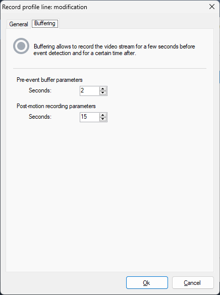 |
Fig. 5.2.4 Setting up a record profile line
Let us consider the main parameters of a recording line. The field «Type» specifies the condition of making a recording. The following options are possible:
-
Constant. When choosing this type the recording will be made without stops, continuously.
-
On motion. Recording will start when the motion detector will detect a motion and the recording will continue for a specific period of time. Also, recording can be switched on and off by an operator (if he has the rights) or by a script.
-
On demand. When choosing this option, recording will be switched on and off manually by an operator (if he has the rights) or by a script.
The field «Stream» allows a profile to choose the most suitable stream of a camera (see the section about setting up camera streams).
The flag «Skip frames when writing to the archive» allows you to enable frame dropping while recording. Enabling this option for a stream in H.265/H.264/Mpeg4 format can lead to a loss of playback smoothness. This is caused by the specifics of these video formats.
The group of elements «Recording on weekdays» allows to specify for which specific weekdays this profile line is active.
When choosing the recording type «On motion» or «On demand» you can specify additional parameters – to set the time period during which it is necessary, to save the video before a detected event (for monitoring actions which have caused the triggering of the event) and to set the time length of recording after the sensor has stopped detecting motions. These parameters can be set up in the tab «Buffering».
5.3 Setting up cameras
In the configurator section «Cameras» you can carry out all operations for adding cameras into the system and setting up the cameras. A list of registered devices will appear in the right window of the application when navigating to this section (Fig. 5.3.1).
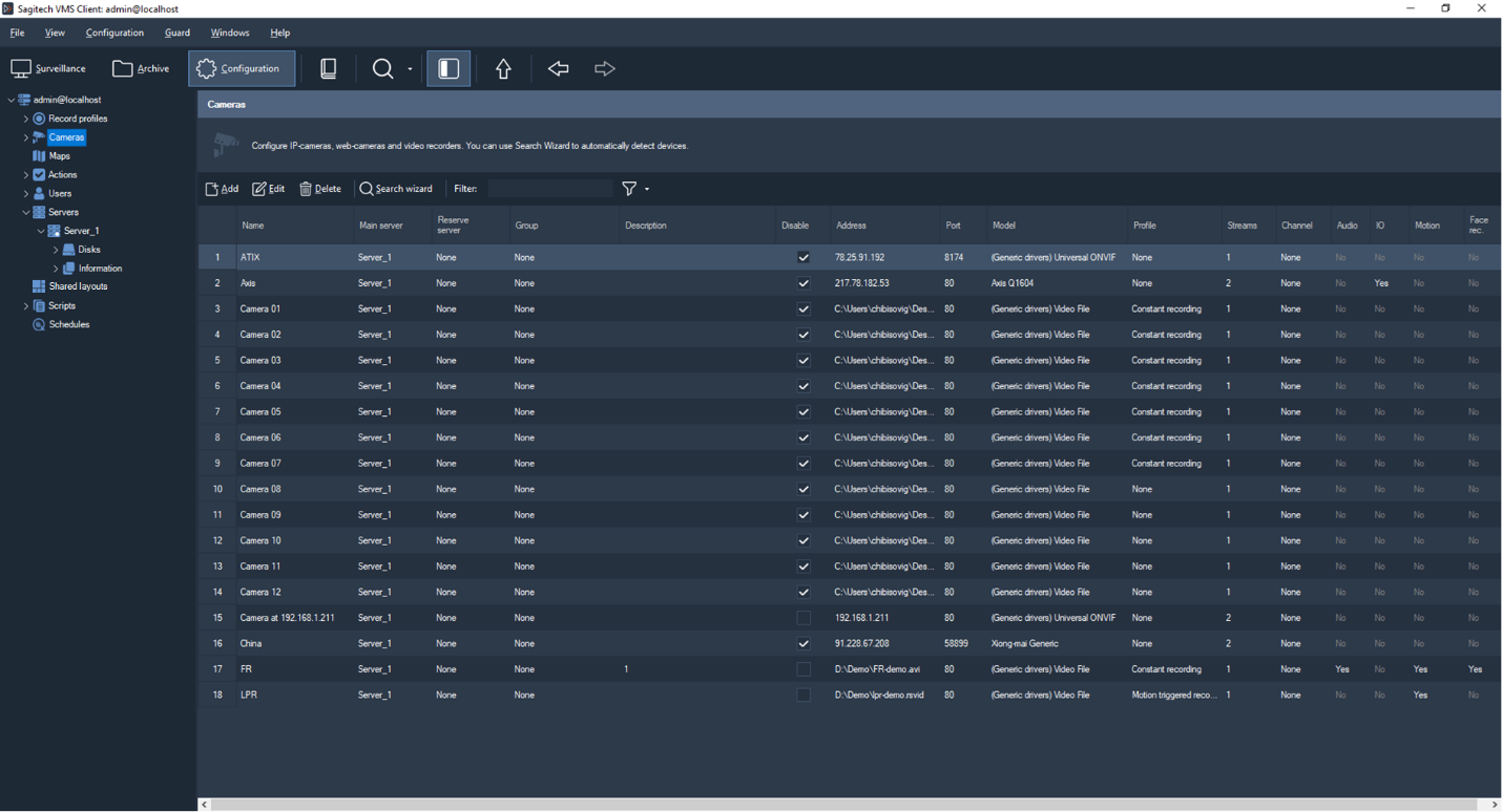
Fig. 5.3.1 The window of editing the parameters of system cameras
It is possible to add cameras both manually (the button «Add»), and automatically with the help of a camera search wizard (the button «Camera search»).
5.3.1 Search for cameras in the network
Camera search wizard allows to automate the process of adding cameras into the system. The following window will be displayed when starting the wizard (Fig. 5.3.1.1):

Fig. 5.3.1.1 The welcome window of the camera search wizard
The wizard can perform search for cameras in two modes: a search with the use of detection protocols and scanning the range of network addresses (Fig. 5.3.1.2).

Fig. 5.3.1.2 Choosing the mode of search for cameras
The first search option uses the ability of cameras to announce themselves in the network with the help of protocols UPnP and Zeroconf. These protocols are not supported by all camera models that are available in the market.
The second search option is the most universal but it is performed longer. It performs sequential scanning of a set range of addresses trying to detect the fact of presence of a device and its model on each address.
After specifying a list of addresses you will navigate to the window of choosing ports (Fig. 5.3.1.3). In a standard way, cameras provide access to Web-interface, obtaining videos in the format Motion Jpeg and separate Jpeg shots on the port 80. The port for receiving video by the protocol RTSP – 554. If the parameters of cameras have been specified anew or if they do not correspond to the accepted ones then input the list of ports separated by commas.

Fig. 5.3.1.3 Setting up of polled port numbers
Then you will proceed to setting up authentication parameters (Fig. 5.3.1.4). Specify the set of pair User name-Password through which the cameras will be accessed and click «Next» in order to start process of searching.

Fig. 5.3.1.4 The window of the parameters of authentication
In the process of detecting devices, they will appear in the list of the search window (Fig. 5.3.1.5). Devices will be highlighted in red if the driver has not been able to match. You can set the driver manually or you can set the authentication parameters and take advantage of the function of automatic recognizing a model.

Fig. 5.3.1.5 The process of detection
You can change the parameters of a detected device by choosing it in the list and by clicking the «Set up» button (if several devices are chosen then group editing will be performed).
If a camera model cannot be recognized unambiguously then you will be offered several options that suit the drivers of this camera. You will be able to choose the necessary driver (model) in the window of settings.
After setting up devices, choose those cameras that need to be added into the configuration with the help of checks and click «Next». Now the wizard has finished its work of adding cameras (Fig. 5.3.1.7). All the added cameras will be accessible in the corresponding section of the configurator.
Fig. 5.3.1.7 Finish of the work of the camera search wizard
5.3.2 Manual setting up of IP cameras
Choose the necessary camera and click the button «Edit» for accessing its characteristics (Fig. 5.3.2.1).
 |
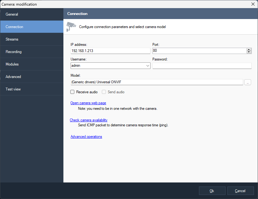 |
Fig. 5.3.2.1 Changing camera settings
In the «General» tab you can specify a unique name of the camera under which it will be accessible in the program, to change the group, description, or to temporarily to disconnect the camera. In a disconnected mode no information is obtained from the camera (accordingly, clients do not receive video and no recording is made).
In the «Connection» tab the data are entered that are necessary for setting up connection to a camera. These parameters depend on camera settings. The parameters «IP Address» and «Port» specify the network address of a camera, «User» and «Password» - parameters of the account through which connection is performed. Also it is necessary to set «Camera model» by clicking the button «…» on the right from the field with the model name. Then the following window will appear:

5.3.2.2 The window of choosing a camera model
Choose the name of the camera maker in the left half of the window and its model in the right half. If you do not remember the camera model or its maker, or you do not know them, you can use the «Detect» button. Pay attention that for the correct detection it is necessary in advance to set an address, a port, a username and a password in the «Connection» tab.
If the necessary camera model is absent in the list, you can use the universal drivers. In order to do this you need to choose «General drivers» in the list of makers, and in the list of camera models you need to choose one of the universal drivers – ONVIF, PSIA, Web camera or «Universal HTTP/RTSP». In the latter case in the line «URL for receiving video» of the «Streams» tab (Fig. 5.3.2.4) the path must be typed for receiving video data from the camera. The parameters of this line can be obtained by reading the documentation for cameras. Also in the case of absence of a camera in the list of supported devices you can address the «Sagitech Lab» support service and this camera will be included into the list of the supported ones.

Fig. 5.3.2.4. Setting up the driver «Universal HTTP/RTSP»
After finishing the process of search you will be offered the list of suitable models. Choose the necessary model from the list and click «Ok».
For many cameras there is a possibility of receiving more than one video stream with different parameters (format, resolution, quality, the amount of frames per second). You can set up the amount and parameters of received streams in the tab «Streams». The advantage of using several video streams provides the possibility of distribution of roles among them. For example, a stream with the video format H.265/H.264/Mpeg4, can be used for recording data into the archive because data with this format take less space, and a stream with the Motion Jpeg format (JPEG) – for outputting an image on the client computers because fewer resources are needed in order to unpack this format. Also different streams can be used for the modes of viewing and recording. Moreover, depending of the needs, streams with different resolution can be used on different clients or in different layouts (by default a stream is chosen automatically depending of the size of a video cell). When choosing the protocol “RTSP (default codec)” for receiving a video, the system uses the video codec that is set in the settings of the camera. The line «Additional parameters of the connection line» allows to specify additional parameters when connecting to cameras. For example, you can set «color=0» for Axis cameras in order to receive a monochrome video stream. You can read the necessary parameters of receiving a video in the documentation for cameras.
Pay attention to the fact that when changing the parameters of receiving an image some cameras might need time for rebooting, when no image will be available from them during the reboot.
In the tab «Recording» (Fig. 5.3.2.6) it is necessary to choose a recording profile which determines the schedule according to which an archive will be kept.
If you plan to make camera recording in the case of appearance of a motion then you need the «Motion triggered recording» profile, to set the kind of the detector (of the server, or embedded in the camera) and to specify its parameters in the tab «Modules» (Fig. 5.3.2.7).
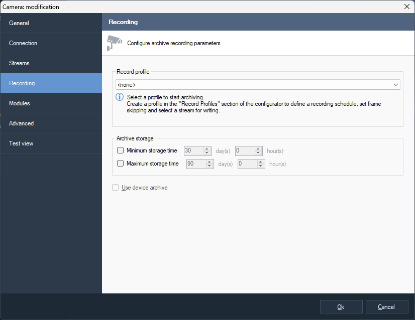
Fig. 5.3.2.6 Setting up the recording parameters of the camera

Fig. 5.3.2.7 Modules tab
The built-in camera detector is set up through Web-interface of the camera, is executed by its software and conveys the information to the server.
The server motion detector is executed directly on the server. Choosing a built-in camera detector allows to decrease the load on the server, while a server detector is universal and independent of the camera model (some camera models do not have a built-in motion detector or they are equipped with a low grade detector).
Click «Settings» in order to determine the parameters of the server motion detector. When this happens a window will appear whose tabs are displayed in Fig. 5.3.2.8.
 |
 |
Fig. 5.3.2.8 Setting up the parameters of the motion detector
This interface allows to specify the following parameters of the motion detector:
-
The stream for analysis. It allows to set the necessary video stream if several of them are received from a camera - it will allow, for example, to specify the stream in the format JPEG/MJPEG for a maximum performance of the motion detector.
-
The minimal size of a detectable object. The value of the parameter can be specified in a percentage equivalent from the size of a film frame and it can be set either in a numerical range (from 1 to 100%), or in a graphical one. In order to do this you need to choose the button «Select», after this a window will appear (Fig. 5.3.2.9), which will allow to choose the minimal size of the detected object with the help of a mouse.
-
The sensitivity of the detector. The value of the parameter is specified within the range from 1 to 100. The higher is the value of this parameter the more sensitive will be the reaction of the detector for a motion.
-
The amount of analyzed frames per second. The value determines how many frames per second will be analyzed by the detector. It is recommended to set high values when a faster detector reaction is needed. The default is “Auto” which means 10 fps when a video analytics module is enabled and 5 fps otherwise.
-
Use video card to decode H.264. Uses video card to decode H.264 video. Allows to reduce CPU usage.
-
To index sizes and location of moving objects. The parameter is used for saving the parameters of moving objects into the archive. It allows to carry out search in the archive according to the object parameters described above.
-
To index visual features of moving objects. It allows to carry out search for an object in the archive according to the features (according to similarity with set images).

Fig. 5.3.2.9 Choosing the minimal size of a detected object
- The «Detection zones» tab provides an opportunity to exclude some part of a frame from processing by motion detector.
Video analytics modules are available only for the Professional version. The modules work together with the motion detector so it is necessary to switch on the server detector in order to use them.

Fig. 5.3.2.10 The settings of analytics modules
Such modules as the human detector and the face detector, make automatic recording of detected objects into the archive for later search in the mode «Search for objects». The rest of the detectors generate alarm or notification events (see detector configuration). You can also configure advanced event processing with the help of a script. For example, in the Fig 5.3.2.11 you can see the window of a script which processes the event «Sabotage detected» (it is generated by the sabotage detector).
 |
 |
Fig. 5.3.2.11 Setting up a response for a sabotage
The tab «Advanced» allows to set up advanced parameters of a camera (Fig. 5.3.2.12). Set «Video channel number» if you connect to a camera with several lenses, or to a video recorder with a few connected cameras. Also on this tab you can specify additional parameters of the protocol RTSP: >: port for connecting to a camera and a transport protocol (these parameters must correspond to camera settings which are set directly through its web-interface; default values are suitable for most cameras).
You can move the process of decoding a video with the format H.264 to a video card by choosing the option «On the video card» in the drop-down list «Decoding H.264». It will allow you to reduce the load on the processor when watching a video in the Sagitech Client application. This functionality supports such video cards as NVidia, ATI, Intel, S3 (you can verify the support of your video card by using DXVA Checker which is a free utility). Different video card models have different restrictions for the amount and parameters (resolution, quality, FPS) of the simultaneously decoded video streams. Because of this, it is not recommended to use this mode for a big amount of cameras - you can evaluate the abilities of your video card by test (to verify the amount of simultaneously watched channels when there is a fall of FPS or the quality of a decoded video).
If problems appear when displaying a video from a camera (in the mode of surveillance or reviewing the archive), choose the option «Universal decoder» in the drop-down list «Decoding H.264». The universal decoder has a higher compatibility with video streams from different cameras but it has a little bit lesser performance than the default decoder.
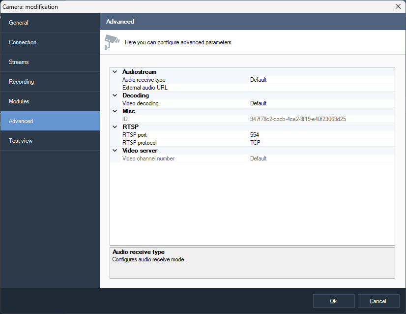
Fig. 5.3.2.12 Setting up advanced camera parameters
The last tab of the camera parameters, «Test view» allows to test the set camera parameters (Fig. 5.3.2.13).

Fig. 5.3.2.13 The window of the test view of the video stream from a camera
Click «Connect» in order to perform a test connection to a camera or «Disconnect» - to disconnect.
Click «Ok» In order to receive the changes after setting up all the parameters of a camera.
You can change parameters of several cameras simultaneously by choosing the necessary cameras in the camera list of the configurator and by clicking «Edit»:
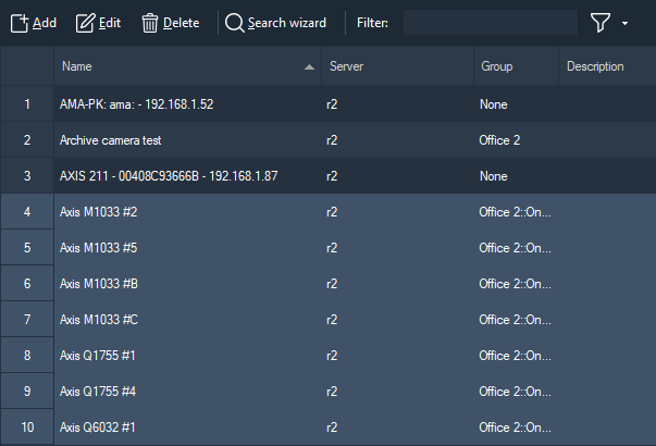
Fig. 5.3.2.14 Editing the parameters of several cameras simultaneously
5.3.3 Setting up Web-cameras manually
In Sagitech VMS there is support for both IP cameras, and Web-cameras. In order to add a Web-camera to the system it is necessary to open the window of adding a camera and to set the camera model «(Generic drivers) Universal Web camera» in the tab «Connection». The tab will have such an appearance as it is shown in the Fig. 5.3.3.1. Choose a video source that corresponds to the camera and, if necessary, an audio source. Pay attention that the numbers of sources can change when making changes in the configuration of devices and, accordingly, it might be needed again to choose the necessary sources in this tab. Examples of such changes are: disconnecting a device from a USB port and connecting it to a different USB port, disconnecting a device, changing a device.

Fig. 5.3.3.1 Setting up the parameters of a Web-camera
Video stream settings (such as a resolution and the amount of frames per second) and recording parameters are set up similarly to the same parameters of IP-cameras in the tabs «Streams» and «Recording».
5.4 Setting up groups of cameras
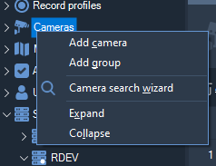
| For convenience, cameras can be united as groups. This uniting is purely logical (for example, you can unite a building, a floor, a department etc.). Choose the item «Cameras» (or a group that exists already) in the tree of the configurator and click «Add group» in order to add a new group (Fig. 5.4.1). |
Fig. 5.4.1 The menu of the camera item |
A group of cameras has only three parameters – its unique name, a parent group and a description. You can change the belonging of a camera to a group (or of a group to a group) with the help of the parameter «Group» in the window of editing an object, or just by dragging the necessary object to the necessary group in the item tree with the help of the operation Drag & Drop.

Fig. 5.4.2 The window of adding a group of cameras
When choosing a group of cameras in the item tree, in the right part of the window only those cameras will be displayed which belong to this group and its subgroups. For example, in the next figure only four cameras are displayed which belong to the group «Office»:

Fig. 5.4.3 Configuring cameras that belong to the group
5.5 Security parameters
Sagitech VMS is a multi-user system that allows to determine different rights of access for different users. Go into the item «Users» in the configurator in order to set up security parameters. By default, in the system there is only an admin user – a system administrator who has the maximal rights. By default the administrator's password is not specified. You cannot delete the admin user or change his access rights.
5.5.1 Setting up groups of users
Users can be united into groups with general security parameters. If users and groups are from a group of a higher level they inherit its parameters and rights of access which can be determined anew on any level. Click with the right button of the mouse on the item «Users» of the configurator and choose «Add group» in order to add a new group of users:

Fig. 5.5.1.1 The menu of the Users section
A group of users has three main parameters – its unique name, a parent group and its description. You can change belonging of an object (a user or another group) to a group with the help of the «Group» parameter in the window of editing an object or just by dragging the necessary object into the necessary group in the item tree with the help of the operation Drag & Drop.
 |
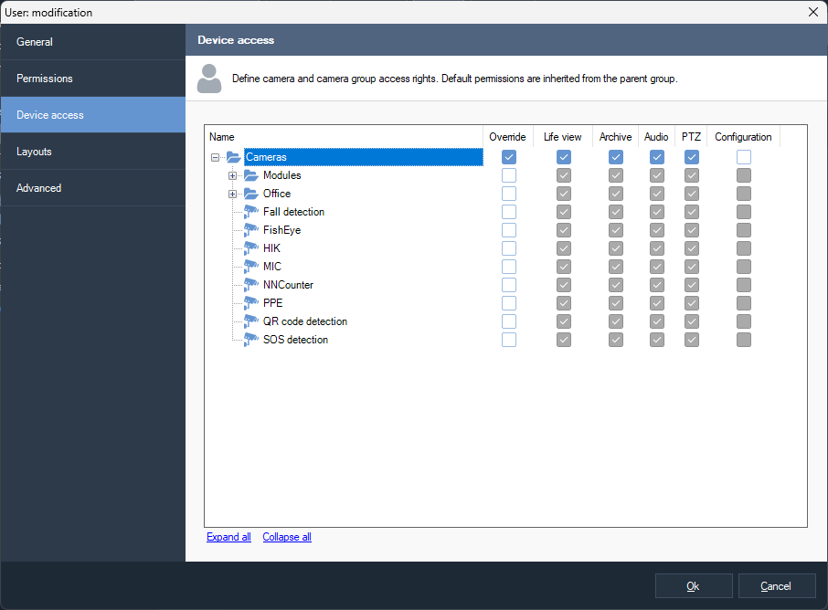 |
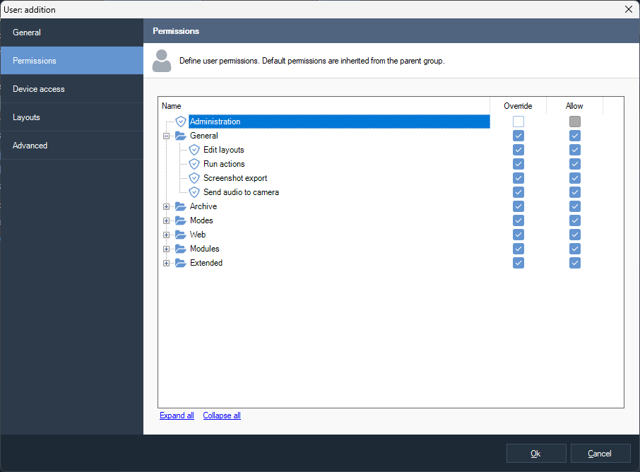
Fig. 5.5.1.2 Setting up permissions and the rights of access
In the tab «Permissions» you can set up permissions of access for this group. Permissions will be applied as default permissions to all subsidiary users and groups. Check «Override» which provides access to the elements of changing the value of the security parameter in order to determine anew the permissions of this group. The group has the following permissions (Table 5.4.1.1.1):
Table 5.5.1.1 Description of the rights of groups of users
| Parameter | Description |
| Administration | It determines if a group user is given rights for access to the mode «Configuration» and changes of any parameters of the server. |
| Layout edit | It determines whether a group user has the possibility of creating, changing and deleting layouts or layouts are set up by the administrator of the system. |
| Archive view | It determines if a user has access to the mode «Archive». |
| Archive recording control | It determines the ability of a user to switch on/switch off recording manually from the mode «Surveillance». |
| Mobile clients and web-interface usage | It determines whether a user is allowed to connect the server through Web-interface, and also from a telephone or a tablet. |
Rights for access to a camera, a group of cameras or all cameras simultaneously can be set up in the «Device access» tab. By default the rights of access are inherited from a group of a higher level. There are the following rights for access:
-
Life-view. Group users can view an image from this camera (a group of cameras) in the real-time mode.
-
Archive. Group users can view archives from this camera (a group of cameras).
-
Audio. Group users can listen to an audio stream from the chosen camera (a group of cameras) - both in the real-time mode and when viewing an archive.
-
PTZ. Group users can control the rotating mechanism of a camera (pan, tilt, zoom) if a camera has such abilities.
The icons of objects are marked with the pictogram
 if the rights of access to the current group are determined for the
objects. The rights of access of an object are determined with the signs
«+» or «-» after the name of an object in the object tree.
if the rights of access to the current group are determined for the
objects. The rights of access of an object are determined with the signs
«+» or «-» after the name of an object in the object tree.
5.5.2 Setting up users
When choosing the item «Users» of the configurator or when choosing the necessary group, a list of users of the system will be presented in the right part of the window. Click «Add» in order to add a new user:
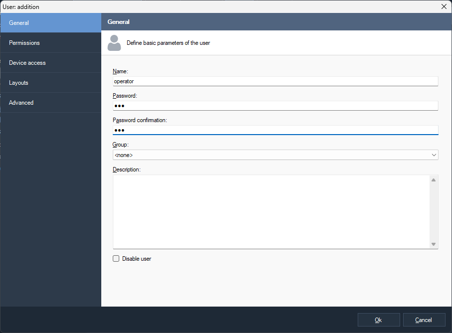
Fig. 5.5.2.1 The window of adding a user
The tab «General» allows to determine the typical object characteristics for an object of the Sagitech system. Determine the unique user name with which he will log in into the system. Input a password in the field «Password» and repeat it in the field «Password confirmation» in order to set the password. Set the group that will include the user.
Pay attention that in the test version the program will not let you set a user password. It is one of the restrictions of the test version that will disappear after activation of the software.
The tabs «Permissions» and «Device access» are completely identical to the similarly-named tabs of user groups. Pay attention that when changing a group that includes the user also a change happens to the inherited rights in the corresponding tabs.
You can determine the user layouts in the similarly-named tab. A layout is called a group of cameras that are located in a specific way and that have specific characteristics. A layout consists of cells and a camera can be put into each of them in order to display a video.
As a rule, layouts are set up from the mode «Surveillance » directly by a user. Although, if there is a necessity to forbid a user to change the parameters of the surveillance mode (see the parameter «Layout edit» of the tab «Permissions»), then for it you can determine the set of layouts in this tab in advance (Fig. 5.5.2.2).

Fig. 5.5.2.2 The tab of layout editing
When adding a new user automatically for him default layouts are created. You can switch off this functionality in the window of application settings (menu File -> Settings, the tab «Configuration»).
Click the button «Add» in order to add a new layout. Then a window will appear on the screen which allows to determine the layout name, its type, the amount and sizes of the cells (Fig. 5.5.2.3).
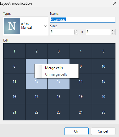
Fig. 5.5.2.3 The window of adding/editing a layout
The button «Edit» edits the type of a layout and its name. Click the button «Configure» in order to determine which cameras will be displayed in the layout cells.
Take into account that changes made by a user cannot be synchronized with the server immediately when modifying layouts of a user who has a right to edit layouts from the «Surveillance» mode. So, if a user continues to work, then in this tab the list of layouts might not be completely relevant. But any changes made by you will be applied immediately.

Fig. 5.5.2.4 The window of layout configuration
Fill the layout cells with the necessary cameras with the help of the button «Select camera». Use the button «Cell properties» if it is necessary to limit the maximal amount of frames per second or to choose the necessary quality of displaying (the necessary video stream). In order to change the location of the cells you can use the operation of dragging (Drag & Drop).
5.6 Event processing (scripts)
The item «Scripts» allows to determine reactions to events of the system, such as loss of connection to a camera, an appearance of a motion, a reaction of the analytics module etc. A script allows to create a connection of an event with a specific list of actions.

Fig. 5.6.1 The section of script determining
The window of script editing consists of three tabs. The basic script parameters are set up in the tab «General».
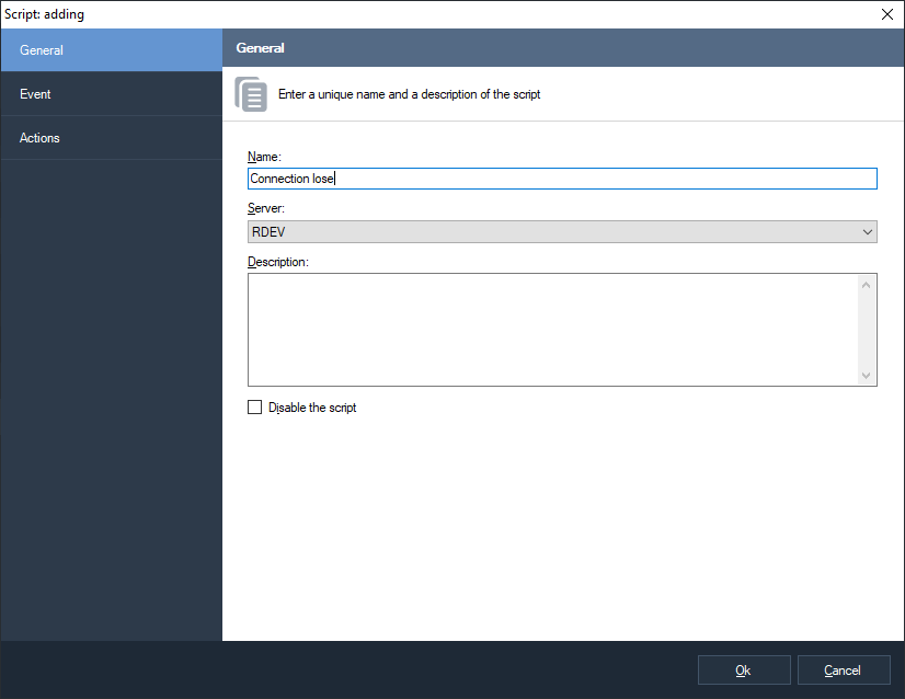
Fig. 5.6.2 The general script parameters
In the tab «Event» you can set up the very event that will cause the reaction of the script. And you can determine a list of cameras for which this event will be applied and the schedule that concretizes the time when this script is relevant.

Fig. 5.6.3 Setting up event parameters
The tab «Actions» allows to determine the list of actions which will be performed if the conditions set in the tab «Event» are fulfilled. Currently the following actions are supported:
-
Sending SMS-messages through GSM-terminal that is connected to COM-port
-
Sending Email-messages
-
Executing an external application on the server
-
Opening a specified HTTP hyperlink (for example, executing a cgi-command)
-
Start to record
-
Stop to record
-
Saving current camera frame to a server directory
-
Uploading current camera frame to FTP
-
Temporal disabling of frame skipping while recording to archive
-
Temporal switching to main stream while recording to archive
-
Generating an alarm (alarms are recorded in the archive and are displayed as an alarm window for clients whose guard mode is activated)
-
Generating a message (messages are recorded in the archive and are sent to clients without an alarm window).
-
Pause between script commands.
-
Set I/O port state for external relay module.

Fig. 5.6.4 Setting up actions
Special variables can be used in the text of the fields and the values of these variables will be automatically substituted when executing an action. For example, when sending SMS with the text “A motion is detected with the %CameraName%” camera, the %CameraName% parameter will be replaced with the real name of the camera.

Fig. 5.6.5 The window of editing the action «Send SMS»
The following variables are supported:
-
Time: %Time%.
-
Date/time is various formats: %TimeFormatD1%, %TimeFormatD2%, %TimeFormatT1%, %TimeFormatT2%, %TimeFormatT3%.
-
Script name: %ScriptName%.
-
Event ID: %EventID%.
-
Event type: %EventType%.
-
Group name: %CameraGroup%.
-
Camera name: %CameraName%.
-
Camera identifier: %CameraID%.
-
Camera address: %CameraAddress%.
-
Last saved frame path: %FrameFilePath%.
-
Report summary result: %ReportSummary%.
For LPR module also available:
-
Plate: %LPR_Plate%.
-
Registration time: %LPR_Time%.
-
Direction: %LPR_Direction%.
-
Entrance: %LPR_Passage%.
-
Weight: %LPR_Weight%.
For face recognition module also available:
-
Person identifier: %FR_PersonID%.
-
Person name: %FR_PersonName%.
-
Registration time: %FR_Time%.
-
Entrance: %FR_Passage%.
-
Similarity factor: %FR_Factor%.
-
Gender: %FR_Gender%.
-
Age: %FR_Age%.
-
State: %FR_State%.
-
External request identifier: %FR_RequestID%.
-
External card number: %FR_CardNumber%.
-
Temperature: %FR_Temperature%.
-
Mask: %FR_Mask%.
-
Liveness factor: %FR_Liveness%.
For PPE detection module also available:
-
Zone index: %PPE_ZoneIndex%.
-
Detected PPE list: %PPE_DetectedTypes%.
-
Missing PPE list: %PPE_MissingTypes%.
For WNR module also available:
-
Plate: %WNR_Plate%.
-
Registration time: %WNR_Time%.
-
Direction: %WNR_Direction%.
-
Entrance: %WNR_Passage%.
-
Weight: %WNR_Weight%.
5.7 Launching user actions
An action is an entity visually represented by a button in the "Surveillance" mode. The action is linked to the script, and allows you to start it by clicking on the button.
Creating and editing actions is available in the Configuration mode.

When adding an action (the "Add" button), the window shown below will appear.

It is enough to specify the name of the action. The "Disable action" flag allows you to temporarily disable the ability to launch an action by removing it from the list of available actions.
In order for an action to perform a specific task, it must be linked to a script. To do this, in the "Scripts" subsection of the "Configuration" mode, you need to create a script with the event type "User action execution".

Click the parameters button to link the script to a specific action.
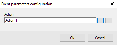
The created actions are available for launching in the objects panel of the surveillance mode. The launch is possible with the context menu, or by double-clicking the left mouse button.

5.8 Information about system condition
The «Information» item of the configurator allows to get information about functioning of the server. It consists of four sub-items.
5.8.1 Event log
In this sub-item you can see a list of events that have happened on the server. By default it displays those events that have happened during the last 24 hours.

Fig. 5.7.1.1 Event log
Click «Search events» in order to load events of a different period of time and also in order to filter them by a source, a type and contents.

Fig. 5.7.1.2 The window of event search
The «Refresh» button refreshes the event list and the «View event» button allows to view information about a chosen event:

Fig. 5.7.1.3 The window of event information
5.8.2 Monitoring disk statistics
The sub-item «Disk statistics» allows to monitor disk statistics in the
real-time mode. In the right part of the window of the configurator you
will see the list of active disks with information about space and the
speed of recording (the amount of frames per second and the amount of
megabytes per). The deactivated disks are marked with the pictogram
 , the problem disks -
 , the normally functioning
disks -
, the normally functioning
disks -  .
.

Fig. 5.7.2.1 Disk usage
5.8.3 Monitoring camera statistics
The sub-item «Camera statistics» allows to monitor camera statistics. The columns «Receive», «Record» and «View» display correspondingly the speeds of receiving video streams from cameras, the speeds of recording video streams on a disk and sending to clients. The data are provided in the following formats: Amount of frames per second / Amount of megabytes per second.

Fig. 5.7.3.1 Camera usage
The camera status is marked with an icon on the right side of the camera
name:  - some data are being
received from the camera and the data are being recordedс,
- some data are being
received from the camera and the data are being recordedс,
 - the camera is deactivated,
- data read error form the
camera.
- the camera is deactivated,
- data read error form the
camera.
5.8.4 Sessions
The sub-item «Sessions» allows to determine client sessions that are set at the moment.
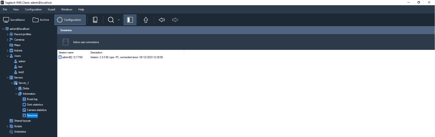
Fig. 5.7.4.1 Session list
5.9 DirectX rendering support
To enable this feature, go to the "File" tab-"Settings" in the "General" section and set the appropriate flag. To make the changes take effect, restart the Sagitech Client.

5.10 Schedules
The schedules subsection allows you to set a schedule for performing certain actions/scenarios specified by the user.

To add a schedule, click the "Add" button and enter a unique name.

In the "Conditions" tab, set the start time of the required actions, the type of repetition, etc.

In the "Actions" tab, the settings are made according to paragraph 5.6.
6 Client: surveillance mode
1 Overview
In order to watch a video from cameras in real-time mode in Sagitech VMS there is a «Surveillance» mode which can be entered by opening the menu «View -> Mode: surveillance». The main window of the program will begin to look like it is shown in the Fig. 6.1.1.

Fig. 6.1.1. The main window of the mode « Surveillance»
In the left part of the window of the surveillance mode there is a control panel that consists of two: «Objects» and «PTZ control».
The section «Objects» consists of two sections («Sessions» and «Layouts») and it allows to control cameras and layouts. A layout is a group of cameras that are located in a specific way and which have specific characteristics of displaying a video. A layout consists of cells and a camera can be put into each cell. With the help of the «Layouts» you can choose the current layout, to add, to edit, to clean and to delete layouts. Also, it is possible to view the archive quickly for all cameras of a layout (Fig. 6.1.2).
In the section «Sessions» you can see a list of cameras that are grouped by connections to the servers of video surveillance. The section allows to edit parameters, to add new parameters and to delete the current cameras and groups (Fig. 6.1.3). Also, you can search for cameras directly from this. Edit and search operations are accessible only to system administrators.
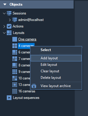
Fig. 6.1.2 The menu of the section «Layouts»
You can quickly add a camera that is chosen in the section «Sessions» into an empty cell of the current layout by choosing the option «Add to an empty cell» of the right-click menu that is activated by clicking this section with the right button of the mouse (this command is also executed with double click). Cameras can be dragged with the help of the function Drag & Drop. If you drag a camera (or a group) inside a section then you can drag it to the necessary group. You can also drag a camera to the necessary cell of a layout in order to add it to this.
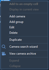
Fig. 6.1.3 The menu of the section «Cameras»
The section «PTZ control» is used for controlling cameras with a turning mechanism and a variable focal-length lens. In real-time mode it allows to control both the camera positioning and the camera focal distance for a detailed view of a necessary object. In the center of the section there is a graphical object with the help of which you can set the motion vector and the turning speed of a PTZ camera. Controlling is performed both from a keyboard (numeric pad), and with the mouse and is performed for a camera being selected in the current layout. The PTZ controls will be disabled for a camera without PTZ support.
The contents of the chosen layout are displayed in the right part of the window. You can choose the necessary layout through the main menu of the application, through the section «Layouts» of the section «Objects» or through the toolbar. In order to display videos, you can fill layout cells with cameras through the menu «Surveillance», the right-click menu of a cell, or through the section «Cameras». After you have added cameras into the cells, their location can be changed by dragging one cell onto another, and then the cells will exchange positions (you must allow the option «Allow cell dragging» of the tab «Surveillance» of the window of the application settings). If you press the button Ctrl while dragging a cell, then the cell will be copied. The ability to edit layouts can be switched off for a user by setting up his access rights in the configuration mode.
6.2 «Surveillance» menu
The «Surveillance» menu provides access to the main commands of this mode (Fig. 6.2.1). It contains both the control elements that depend on the chosen cell of the current layout and general ones for all cells.

Fig. 6.2.1 Menu «Surveillance»
The commands included in the menu «Surveillance» duplicated in the right-click menu that is activated by clicking on a layout cell with the right button of the mouse and also on the toolbar. In the table 6.2.1 you can see the description of the purpose of these elements.
Table 6.2.1 The main control elements of the menu «Surveillance»
Menu option (control element) |
Hot keys | Purpose |
| Maximize | Enter | It maximizes the image of the camera that is chosen from the layout. |
| Select camera | Ctrl+A | It chooses a camera for displaying in the current cell of the layout. |
| Clear the cell | Ctrl+L | It clears the chosen layout cell from the camera that is connected with the cell. |
| Cell properties | Ctrl+P | It activates a menu in order to change the parameters of a view cell. |
| Archive view | Ctrl+R | It allows to switch a cell to the archive view mode (the left button of the mouse), or to view the archive for this camera in the «Archive» mode (the middle button of the mouse). |
| Search camera archive | Ctrl+Shift+F | It switches to the search mode and chooses the camera that is displayed in the cell. |
| Freeze | Ctrl+F | It freezes the current video frame from the chosen camera. |
| Play audio | Ctrl+Y | Play audio (it is accessible if audio reception is activated for the chosen camera in the window of its settings). |
| Zoom in | Ctrl+Plus | It zooms in (digital zoom). |
| Zoom out | Ctrl+Minus | It zooms out (digital zoom). |
| Start recording | It starts recording onto the archive. It is available for cameras with the types of recording: «At the request» and «From a motion». A user has to have the permission «Archive recording control». | |
| Stop recording | It stops the recording into the archive that was started earlier. | |
| Show panel | F4 | It allows to hide the control panel that is located in the left part of the surveillance window. |
| Edit camera properties | F12 | It allows to edit the camera settings of the current layout cell. In the sub-section «Setting up cameras» of the section «Configuration mode» you can see detailed description of the camera settings. |
A dialog window appears (Fig. 6.2.2) when activating the option «Cell properties». It allows to set up the cell properties in a more detailed way: to choose a camera for displaying, to switch on or to switch off audio, to reset default display parameters (default parameters are determined in the tab «Video» of the program setup window):
-
Show detected motion. Activate this option in order to put red rectangles around moving objects (in the camera settings the motion detector has to be activated).
-
Show analytics. Activate this option in order to mark detected objects and to display module messages (for example, «Sabotage detected»).
-
Limit the maximum number of frames per second. It allows to «shorten» the stream from a camera. Pay attention that if to decrease the amount of frames excessively then it might cause «jumps» when displaying a video in the formats H.265/H.264/Mpeg4.
-
Frame proportions. It allows to adjust the video stretching within the cell.
-
Display sub-stream when cell size is less than, px. It allows to set a cell pixel size with which streams will switch over. If the size of a cell is bigger than the set value then there will be an output of an additional stream, if smaller – the main one. If the check is absent then the main stream will be displayed always. If the maximum value (1000) is set then an additional stream will be displayed always.

Fig. 6.2.2 Cell properties
6.3 Menu «Layouts».
Menu «Layouts» provides access to the functions of the layout control of the current user. It allows to switch between the current layouts and also to edit the list of layouts. Any layout can be sent for view to a separate window. The commands that are included in the menu «Layouts» are shown in the Fig 6.3.1. The main purpose of the commands is explained in the table 6.3.1

Fig. 6.3.1 The commands of the menu «Layouts»
Table 6.3.1. The main control options in the Layouts menu Sagitech VMS
Menu option (control element) |
Hot keys | Purpose |
| Select layout | It allows to select the necessary layout from the list of existing layouts. | |
| Previous layout | Ctrl+Left | It activates the previous layout from the list of layouts. |
| Next layout | Ctrl+Right | It activates the next layout from the list of layouts. |
| Layout archive | Ctrl+Shift+R | It allows to view the archive of the active layout. |
| Add layout | Ctrl+N | It allows to add a new layout to the list of layouts. |
| Edit layout | Ctrl+E | It allows to edit the settings of the current layout. |
| Clear layout | It allows to clear all the cells of the current layout. | |
| Delete layout | Ctrl+D | It allows to delete the current layout from the list of layouts. |
By default for every new user a set of preset layouts is created (automatic creation can be deactivated through the application settings). You can add a new layout and also to edit and to change the existing ones through the corresponding menu options. A corresponding window will be displayed on the screen when adding/changing (Fig. 6.3.2).
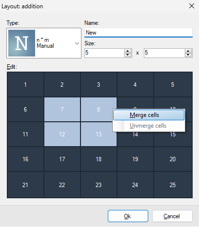
Fig. 6.3.2. The window of adding/changing a layout
Every layout has a unique name and a type. The type determines the amount, the sizes and the location of view cells. You can use one of the preset types or you can set up manually layout parameters that you need. Choose the type «n*m» and input the necessary amount of cells in horizontal direction and in vertical direction in the fields of the group «Size» in order to set up manually. Then in the control element that is called «Edit» you can set up the sizes of cells more precisely with the help of a right-click menu.
6.4 Menu «Export»
The commands of the «Export» menu (рис. 6.4.1) allow to control the current frame of a stream from a camera. It is possible to save with an edited name, to save quickly, and also to copy the current frame of the video stream to the clipboard. By default the «YY-MM-DD-hh-mm-ss.Jpg» format is used when saving a frame and also when saving quickly as a file with a name. Also the Windows file explorer can be activated from the export menu. The «Export video» option is accessible only if the marked layout cell is in the archive view mode.
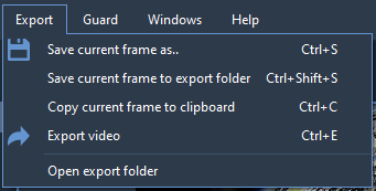
Fig. 6.4.1 The commands of the menu «Export»
6.5 «Guard» menu
The guard mode is active when alarm events generated by the server are displayed in the video surveillance screen of the clients. The output of alarm events is set up with the help of scripts by the administrator of the video surveillance system. An alarm allows to attract an operator’s attention to the camera the video of which is not currently displayed on the screen. The «Guard» menu (Fig. 6.5.1), which is accessible from all modes, allows to control the reception of alarms.

Fig. 6.5.1 The commands of the menu «Guard»
The «Guard mode» option activates the window of guard settings (Fig 6.5.2). This window allows to activate/to deactivate the guard mode and to select cameras which should be set in the guard mode. If the guard mode is not activated for the camera then its alarm events will not by processed at this client point.

Fig. 6.5.2 The window «Guard mode settings»
When an alarm happens, displaying of this alarm will depend on the displaying of a video stream from a camera on the screen at the moment (at least on one of the monitors), or there is no video stream:
-
If surveillance mode is enabled and the camera is displayed on the screen then an alarm text message will be displayed on top of the camera cell. The text automatically disappears in a while.
-
If the camera video stream is not visible at the moment then an alarm message will appear in the upper part of the main window of the program (Fig. 6.5.3).
7 Client: archive view mode
7.1 Overview
The «Archive» mode is used in order to view a recorded video in Sagitech VMS. In order to switch to this mode it is necessary to use the «View -> Mode: Archive» menu option or the «Archive» button on the toolbar. Switching to this mode will be blocked for those users for who the «Archive view» setting is disabled in the access rights. When switching to the archive view mode the application main window will have the following appearance (Fig. 7.1.1):

Fig. 7.1.1 Archive view window
In the left part of the window there is a control panel where you can see the panel of choosing a camera and a list of records. A record is a continuous stream of video frames whose saving in the archive was initiated by a specific event. For example, when recording «from a motion», in this list you will see temporary intervals during which an activity was observed in the zone of the recording of the camera. The record of the currently displayed frame is highlighted. There will be a switch to the beginning of the record when clicking the necessary record.
In the bottom part of the window there is a time scale that allows to view graphically the time distribution of the records and to switch to the record you are interested in. You can change the scope of displaying with the help of the commands of the right click menu of the scale.
In the «Archive» menu you can find the main operations of work with the archive. The «Navigation» menu contains commands for navigating through the archive and the «Export» menu allows to save/copy frames and to export a part of the archive to a file. The most used elements are located on the control panel and in the right click menu that is activated by clicking the work field of the archive view module with the right button of the mouse. In the table 7.1.1. you can see the purpose of the elements of work with the archive and also a correspondence between the menu elements and the shortcut bar with available key combinations.
Table 7.1.1 The functional purpose of the menu elements of the archive module Sagitech VMS
| Menu | Menu option (control element) |
Hot keys | Purpose |
| Archive |
|
It allows to select a camera to view the archive in the current cell (Fig. 7.1.2). | |
| Clear a cell | It clears the selected layout cell from the camera that is connected with it. | ||
|
It selects the layout to view the archive in all its cells. | ||
|
It refreshes the contents of the archive view window. | ||
|
It plays the video stream forward with a selected speed from the moment of the stop of the video. | ||
|
It plays the video stream back with a selected speed from the moment of the stop of the video. | ||
|
It pauses the play of the video stream. | ||
|
Space | It plays forward or pauses a video stream depending on its condition. | |
|
Shift + Space | It plays back or pauses a video stream depending on its condition. | |
|
Ctrl+Shift+F | It switches to the search mode and chooses a cell that is the camera that is displayed in the cell. | |
|
Plus | It increases the speed of playing. | |
|
Minus | It decreases the speed of playing a video. | |
|
Ctrl+Y | Switching on the sound play. | |
|
F4 | It hides or displays the control panel. | |
|
F3 | It hides or displays the time scale of navigation through the recorded data. | |
|
Ctrl+Plus | It zooms in an image. | |
|
Ctrl+Minus | It zooms out the current image. | |
|
It activates the window of editing the camera settings. | ||
| Navigation |
|
Ctrl+G | It allows to choose the necessary date and time for viewing the archive of the current camera. |
|
Ctrl+Up | It allows to go to the next record within the archive of the current camera. | |
|
Ctrl+Down | It allows to go to the previous record within the archive of the current camera. | |
|
Ctrl+Right | It allows to go to the next frame. | |
 Previous
frame Previous
frame |
Ctrl+Left | It allows to go to the previous frame. | |
| Export |
|
Ctrl+S | It allows to save the current frame in the JPEG format. By default the name of the file has the «YY-MM-DD-hh-mm-ss.Jpg» format. |
|
Ctrl+Shift+S | It saves a frame into the directory in the YY-MM-DD-hh-mm-ss.jpg format. | |
|
Ctrl+С | It put the current frame into the clipboard | |
|
Ctrl+E | It allows to export a video. | |
| Open the file explorer | It opens Windows file explorer. |


Below you can see the window if navigation through cells for which there are data in the archive (Fig. 7.1.2). User rights determine presence of cameras in this window. In the left part of the window there is a list of cameras (in the figure in the list there is only one camera because the user has rights of access only for this camera).
This window provides an opportunity to filter by a camera name with the filter that is located in the upper part of the window which considerably simplifies the search when there is a big amount of archive copies from many cameras.
On the right there is an element of preliminary view of a video from a selected camera, and in the bottom – information about the time range for which there are records for this camera.
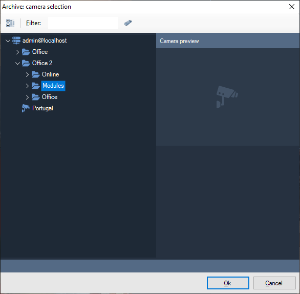
Fig. 7.1.2 Selecting a camera for viewing an archive.
When entering the archive view mode and selecting a camera, by default, it will load records from the camera for the current 24 hours. You can switch to a different date or time by using the switch window (Fig. 7.1.3).

Fig. 7.1.3 Time navigation window
You can watch a recorded window from a few cameras simultaneously. In order to do this you need to click the button of choosing a layout on the toolbar and then you need to select the necessary layout in the window that has appeared (Fig. 7.1.4).

Fig. 7.1.4 Layout selection window
If the selected layout contains several cameras, then the list panel will contain sets of records for every camera and the time scale will display the records of all the cameras simultaneously with highlighting the record of each camera in a separate color (Fig. 7.1.5).
You can change the cameras that are displayed in the layout cells in the same way as in the surveillance mode. Pay attention that changes will not be applied to the layout itself but only to its current image in the archive.

Fig. 7.1.5 Viewing several cameras in the archive
7.2 Video archive export wizard
In Sagitech VMS it is possible to export data from an archive to a video file. In order to do this you need to start a video archive export wizard by using the corresponding menu option that is called «Export» (See table 7.2.1). After starting it a welcome window will appear (Fig. 7.2.1).
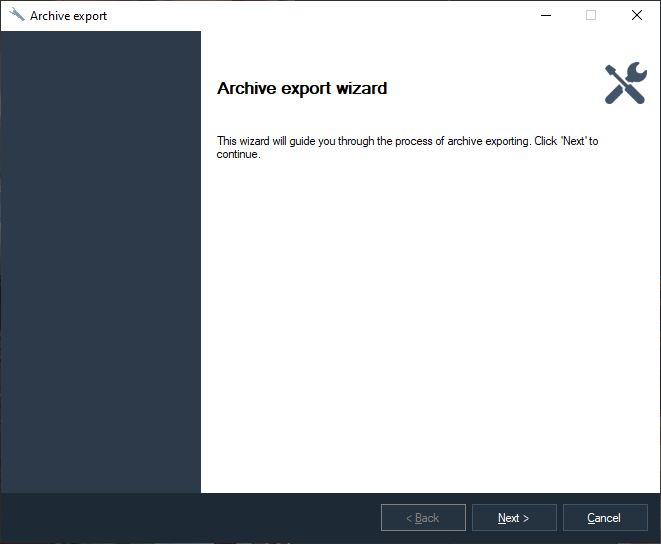
Fig. 7.2.1 The welcome window of the video archive export wizard
After clicking the «Next» button the wizard will offer to select the time range during which it is necessary to export video data (Fig. 7.2.2).
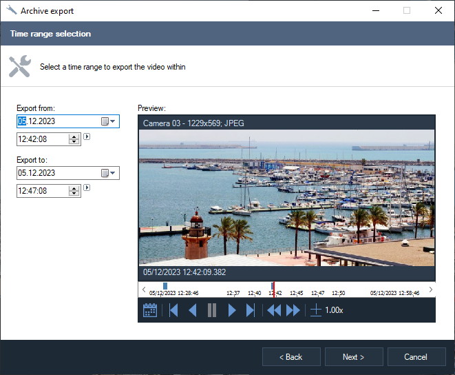
Fig. 7.2.2 The window of selecting the export boundaries
At the next stage of the work of the wizard you will need to select the format: the export is possible both into the inner Sagitech video format and into the format of AVI or MP4 video files.
In order to play files of the first type you need the Sagitech VMS Player, whereas any player will be suitable for the second and the third types (when moving a video to a different computer it is necessary to make sure that the necessary codecs are installed on it).
When exporting to the AVI format there will be an execution of unpacking and the video data will be compressed again into the format demanded by the codec, whereas when exporting to the Sagitech video format or to the MP4 format there will be no need to execute such operations. That is why it takes a much more time to export to the AVI format.

Fig. 7.2.3 The window of selecting the export format
After selecting the export format it is necessary to determine the parameters of the exported video: for Sagitech Video – it is a maximum amount of frames per second (Fig. 7.2.4), and for AVI video files – the resolution, the amount of frames per second and the codec which will be used to compress this video (Fig. 7.2.5). You can configure the selected codec by clicking the «Parameters» button. By default, Sagitech Mpeg-4 Codec is used which is embedded into the application.

At the next stage you will be offered to specify the name of the file to export the video to (Fig. 7.2.6).
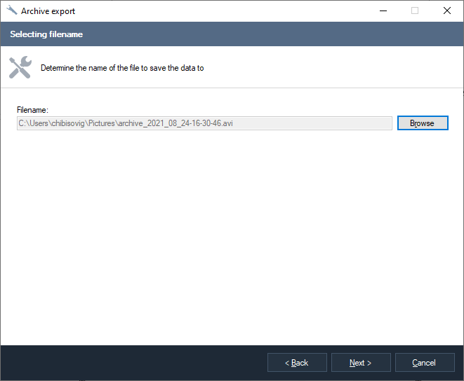
Fig. 7.2.6 The window of selecting a filename
After selecting a filename and clicking the «Next» button the wizard will start the export. A window will appear which will display the process of executing this operation (Fig. 7.2.7). The export might take a long time which depends on the settings of the work of the wizard that were selected at the previous stages: the format, the codec and the time range of exporting.

Fig. 7.2.7 Exporting a video archive to a file
The window of ending the work of the wizard will be displayed after a successful completion of the export (Fig. 7.2.8). If the «Open file in Window explorer» check box is selected, then, when clicking the «Finish» button, Windows Explorer will be opened with the created highlighted video file in it.
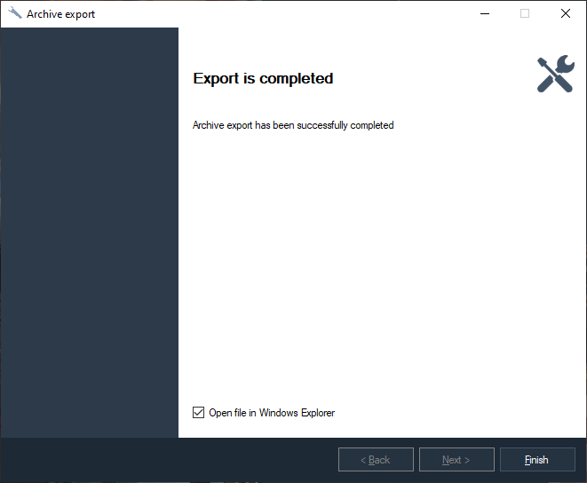
Fig. 7.2.8 The wizard window of the completion of the export of the video archive.
8 Archive search
8.1 Overview
In Sagitech VMS it is possible to search for events and objects in an
archive (Fig. 8.1.1). In order to search it is necessary to switch the
corresponding mode by choosing the «View -> Archive search» menu option
or by using the toolbar icon  . It is possible to switch
quickly to the search mode by a specific camera from the surveillance
mode and the archive view mode.
. It is possible to switch
quickly to the search mode by a specific camera from the surveillance
mode and the archive view mode.

Fig. 8.1.1 Archive search window
In the right part of the window a list of found elements is displayed, in the left part there is a panel that allows to set search parameters and to view an archive from the moment of the appearance of an object or an event. There are two modes of search: search for objects and search for events. The search mode is selected with the help of the Mode drop-down list. Such parameters, Time range and Cameras can be applied to both the modes, the other parameters differ from one another.
When setting up the search time by an archive you can set the range
manually or you can click the  button for choosing the
preset value and in the context menu (Fig. 8.1.2) that will appear you
can select the necessary interval. This menu is also displayed when
clicking with the right button of the mouse the element of inputting a
date or time.
button for choosing the
preset value and in the context menu (Fig. 8.1.2) that will appear you
can select the necessary interval. This menu is also displayed when
clicking with the right button of the mouse the element of inputting a
date or time.

Fig. 8.1.2 The menu of interval selection
The search can be performed simultaneously from several sources
(cameras). By default the search is performed from all cameras. In order
to select a specific camera, check the checkbox of a Camera and click
the parameter setting button ( ). Then the selection window
will appear on the screen (Fig. 8.1.3). Pay attention that when
selecting several cameras for search the «Search area» option becomes
unavailable.
). Then the selection window
will appear on the screen (Fig. 8.1.3). Pay attention that when
selecting several cameras for search the «Search area» option becomes
unavailable.
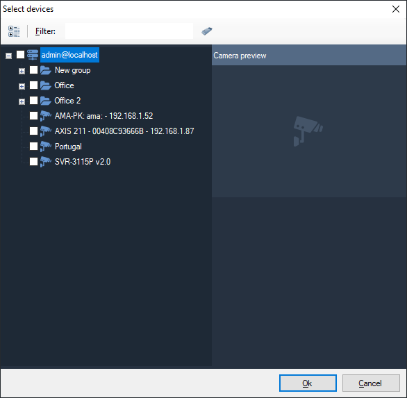
Fig. 8.1.3 Selection of cameras for search
For convenience of watching an archive video, the archive view element
can be maximized for the entire size of the window of the program with
the help of the button  .
.
8.2 Object search
Object search (рис. 8.2.1) is an intellectual search that allows to find objects detected by a motion detector or analytics modules (detector of people, faces etc.). When searching it is possible to select objects in accordance to the following characteristics:
-
Time range during which the archive search will be performed
-
Cameras that participate in the search
-
Search area
-
Minimum size of the searched object
-
Maximum size of the searched object
-
Visual similarity (search by similar images)
For the search of moving objects it is necessary to enable object indexing in the settings of the server detector of a camera (cameras), and for the search of objects detected by the analytics module – to enable this module in the camera settings.
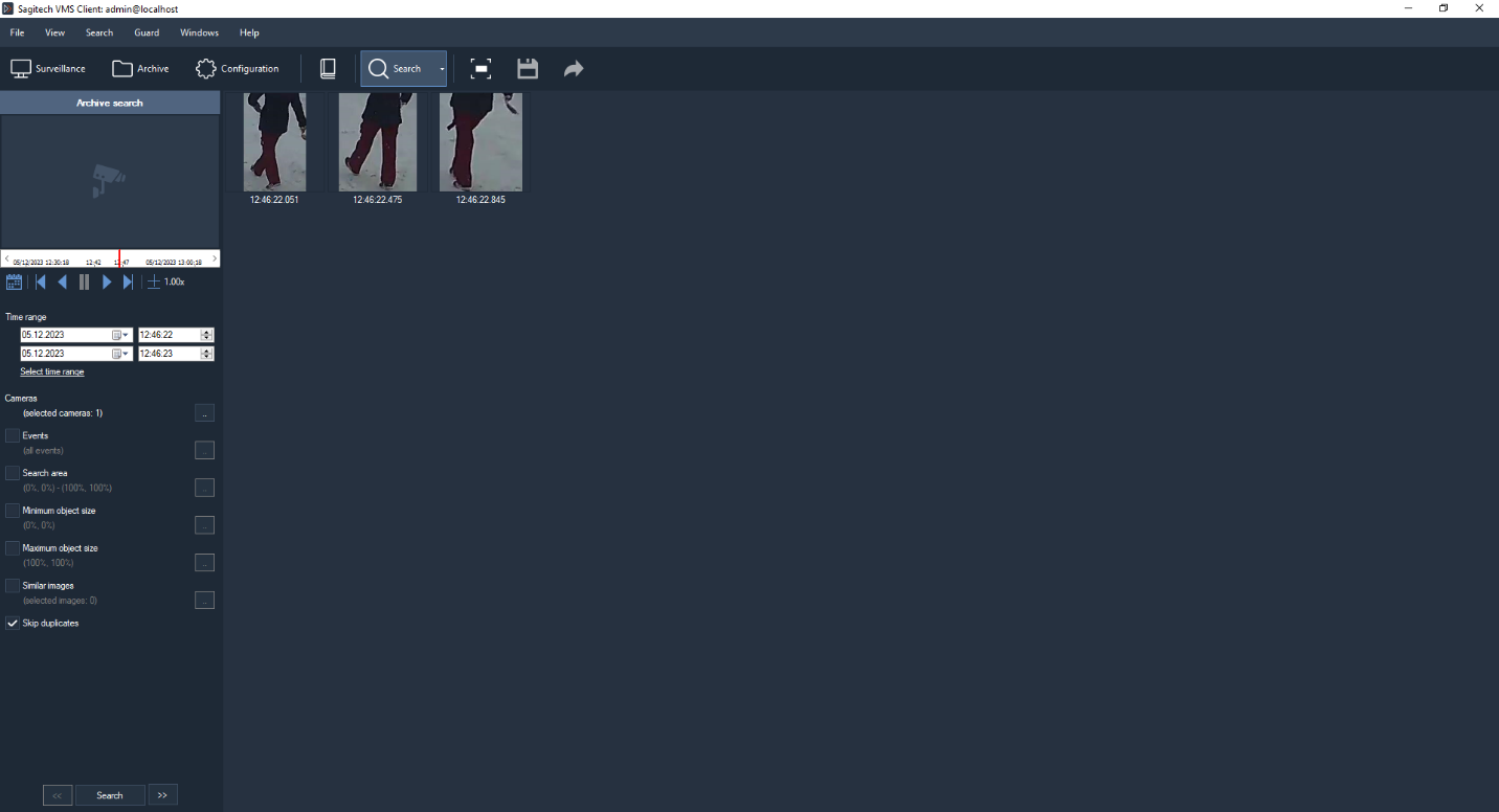
Fig. 8.2.1 Object search mode
The search area is set up by selecting the necessary search area with the help of the mouse cursor and this area will be marked with a rectangle that has red sides (Fig. 8.2.2)

Fig. 8.2.2 Setting up search area
Setting up the maximal and minimal sizes of the search object is performed similarly to the setting up of search area.
Search by similar images allows to search in the video archive by set images which allows to reduce considerably the time of searching the necessary objects inside an archive. When clicking the button of setting up similar images, a window will appear that will allow to add or to delete images (Fig. 8.2.3).
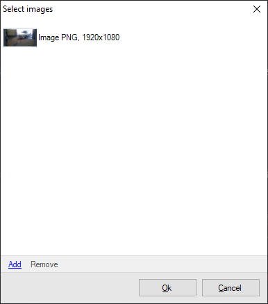
Fig. 8.2.3 Selection of similar images
In order to load an image and to perform the search by the parameters of the image it is necessary to click «Add» and then to choose the necessary image on the necessary data medium.
In the right part of the window (Fig. 8.2.1) you will see the found images that correspond to the selected search conditions. You can navigate through the found images within a few pages either by clicking the buttons «Forward»/«Back» or with the help of the key combinations Ctrl+Right and Ctrl+Left accordingly.
A context menu will appear when clicking any of the found images with the right button of the mouse:
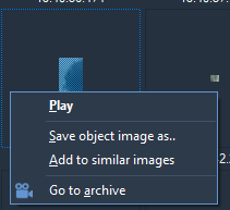
Fig. 8.2.4 The context menu of the found objects
The menu allows to start playing the archive from the moment of the detection of the object, to save the selected image as a separate file, to add this image to the images whose parameters are used for search through the archive, and also to switch to the frame with the selected image by opening it in the window of the «Archive» mode.
8.3 Event search
Event search (Fig. 8.3.1) allows to find alarm events and messages in the archive for a specified period of time.
An event has to get the status of alarm or a message in order to be recorded to the archive. For this purpose it is necessary to process it with the help of a script – the script has to be connected with the event type and it has to contain the actions: Initiate alarm or Initiate message. Recording of events is made only to the server event log if the events have not been processed with scripts.
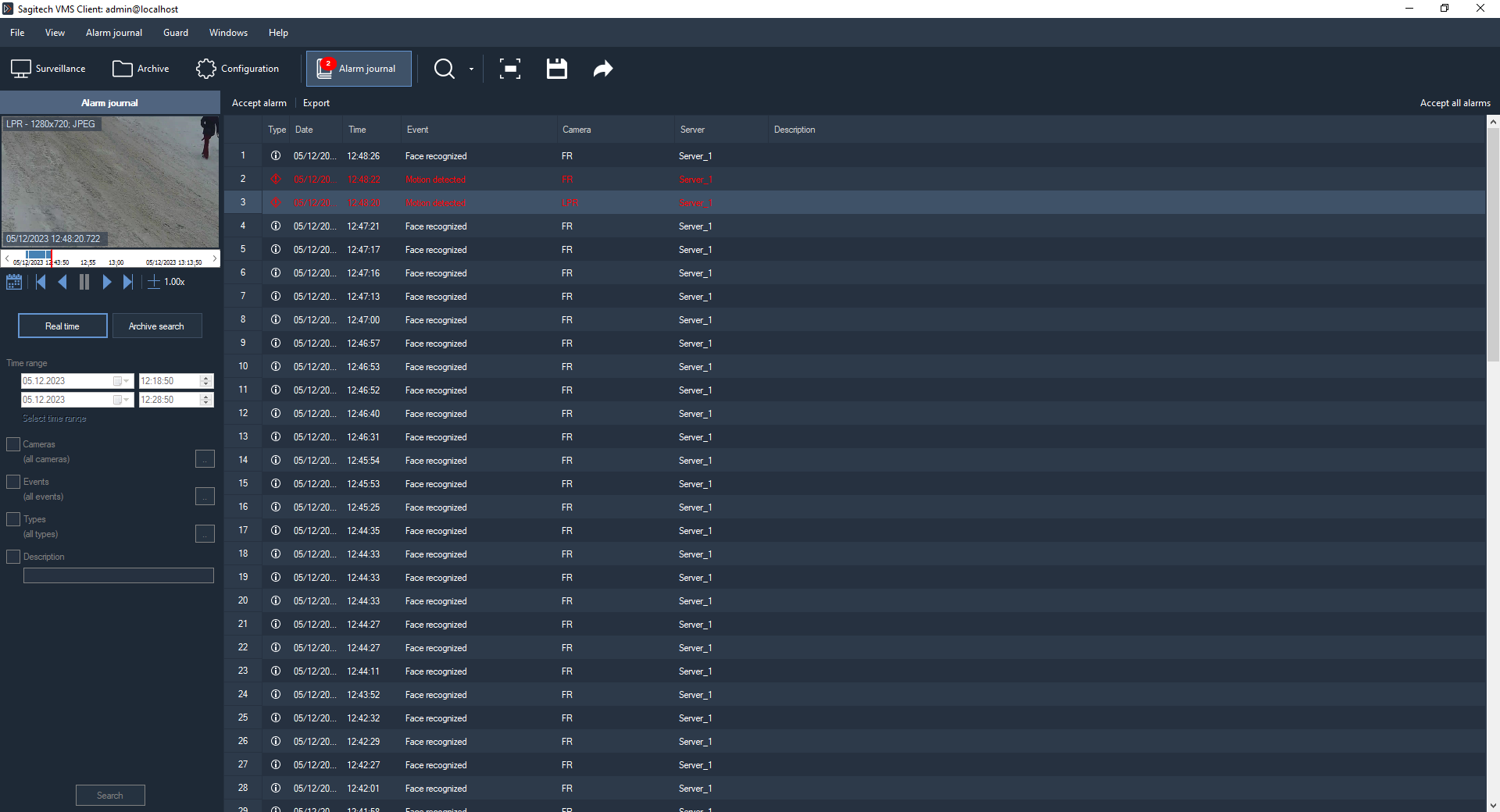
Fig. 8.3.1 Event search mode
Event selection is made according to the following parameters:
-
Event kinds (for example, Face detected, Sabotage detected, Smoke detected etc.)
-
Event types (Alarm or Message)
-
Description (some events contain extended data that are presented in the interface in the form of a description).
9 Sagitech Video file player
9.1 Overview
Sagitech VMS Player is used for the purpose of viewing the video files that have been exported to Sagitech Video format. This application is installed together with the client of the Sagitech VMS video surveillance system.
The application can be started from the «Start» menu (Start->All programs-> Sagitech Video Management System -> Utilities -> Sagitech VMS Player) (Fig. 9.1.1), or double clicking on any file that is exported to the Sagitech Video format.
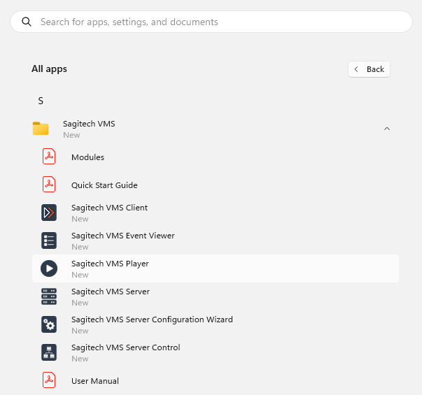
Fig. 9.1.1 The start of Sagitech VMS Player
9.2 Usage
After you have started Sagitech VMS Player, the main window of the application will appear on the screen (Fig. 9.2.1).

Fig. 9.2.1 The main window of Sagitech VMS Player
The control elements of the player are quite similar to the control elements of the Sagitech VMS Client application. The commands are available through the main menu of the application, through a context menu that is activated by clicking with the right button of the mouse, hot keys and the play control menu in the bottom part of the screen. In the table 9.2.1 you can see the purpose of the commands by an example of a menu:
Table 9.2.1 The functional purpose of the elements of the menu of the video player.
| Menu | Menu option (control element) |
Purpose |
| File | Open a file | It activates the window of opening a video file |
| Close | It closes the open video file | |
| Export to AVI | It exports the necessary fragment to the AVI format. | |
| Exit | Exit from the application. | |
| View | Full-screen mode | To switch to the full-screen mode. |
| To stretch the image without changing of proportions | It sets up the video output parameters: if the video output area is larger than the size of the frame then the frame will be stretched to the size of the area but the correlation between its width and its height will not be changed. | |
| To stretch the image with changing of proportions | To stretch frames of a video stream to the size of the area with changing of the correlation between the width and the height. | |
| Not to stretch the image | Not to stretch frames of a video stream. | |
| Play | Play forward | It plays the video stream forward with a selected speed from the moment of the stop of the video. |
| Play back | It plays the video stream back with a selected speed from the moment of the stop of the video. | |
|
It pauses the play of the video stream. | |
|
It plays forward or pauses a video stream depending on its condition. | |
|
It plays back or pauses a video stream depending on its condition. | |
|
It increases the speed of playing a video. | |
|
It decreases the speed of playing a video. | |
| Navigation |
|
It allows to go to the next frame. |
| Previous frame | It allows to go to the previous frame. | |
| Help | About the program | To show the information about the program. |
The scale of scrolling allows to skip through the video and it displays the periods of recording from a camera: the dark areas mean the presence of recorded data in a time period, the light areas – absence of data.
10 Interactive maps
10.1 Review
Sagitech VMS Professional provides the "Interactive Maps" functionality, which allows you to display a user-selected image (plan, map, etc.) and place cameras on it. When an alarm event occurs, the camera flashes and the user can open the video stream to detect the cause of the alarm.
It is necessary to enable "Security mode", the menu item "Security -> Security mode.
To hide the camera title, go to the "File"-"Settings" tab and set the appropriate flag.

To switch to the mode of the same name, select the menu item "View ->
Interactive Maps", or use the icon  .
.

10.2 Edit mode
To switch to the interactive maps editing mode, select the menu item "View -> Configuration Mode-> Interactive Maps".
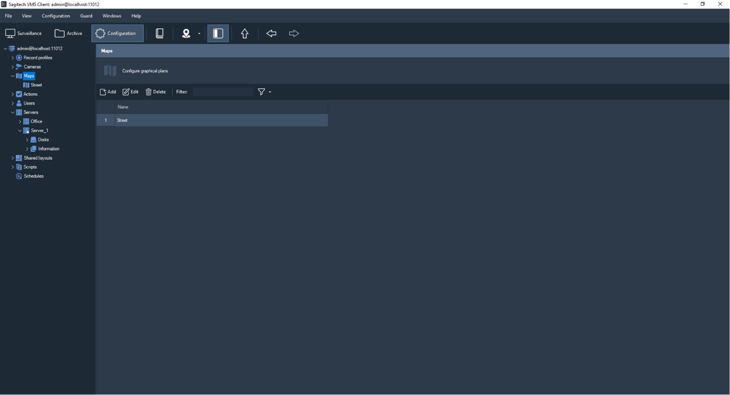
In this window, you can add, delete, edit and filter maps. To add a map and go to the edit window, click the "Add" button.

In the "General" tab, you must specify the name of the map, in the "Map" tab, a list of servers and cameras is displayed on the left, and the map workspace is on the right.
By clicking on the "Upload image" button, you can upload a file in the following formats: JPEG, PNG, TIFF.
"Object size" allows you to set the size of the camera icon (small, medium, large).
The "Auto-size" button adapts the image to a larger or smaller size than the display window, while maintaining the proportions of the original image.

To add a camera to the map, click the "Choose cameras" button.
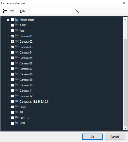
To remove the camera from the map, right-click on the camera icon and select "Delete from map". The video stream is displayed in the context menu.
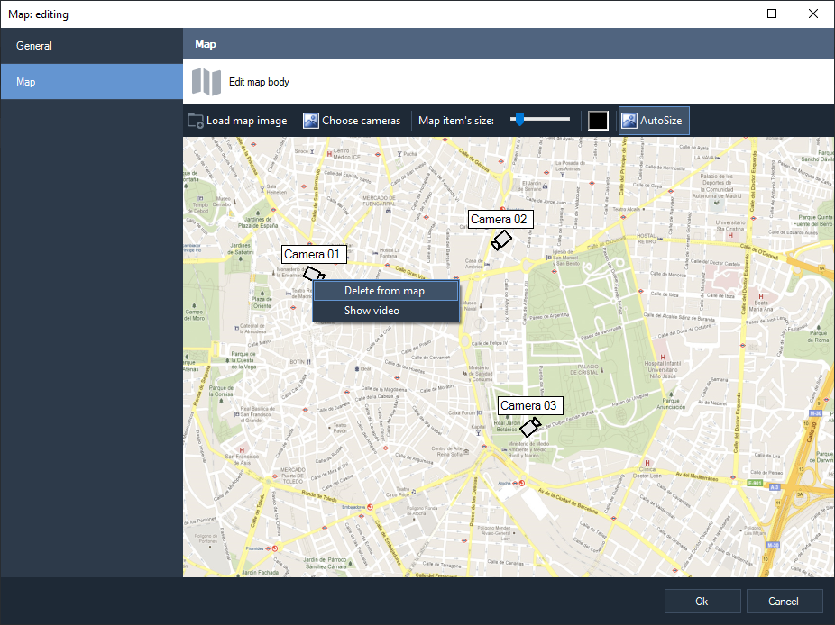
10.3 View mode
To switch to the interactive maps view mode, select the menu item "View
-> Interactive Maps" or use the icon .
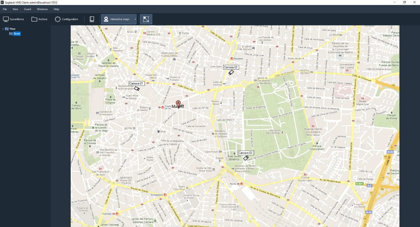
During an alarm event, the camera icon flashes red, and the camera name is replaced by the event name.
The first left mouse click resets the alarm notification, the second opens the video stream.

Double-clicking on the video stream allows you to switch to full-screen display mode, the "Close" button (also double-clicking and the "ESC" button) allows you to exit full-screen mode.

11 Connecting to the server with web-client
11.1 Review
It is possible to connect to the Sagitech server with web-client. By default, the HTTP server that accepts connection data is inactive, but you can enable it using the Server Configuration Wizard. The wizard also allows you to set the port number on which connections will be accepted (by default, it is 11012). In order to connect to the server with web interface, you must enter the network address (or domain name) of the Sagitech server and the aforementioned port number separated by a colon in the browser address bar (for example “http://192.168.0.1:11012 ”), after which the authorization page will appear.

After entering your username, password and clicking the "Login" button, you will be redirected to the real-time surveillance page. For viewing in this mode, your own layouts are available through the browser, as well as through the Sagitech VMS Client. You can select the cameras needed for playback by pressing the RMB through the context menu. Please note that these changes to browsing layouts are not saved to the server and will be lost after the end of the Web session.
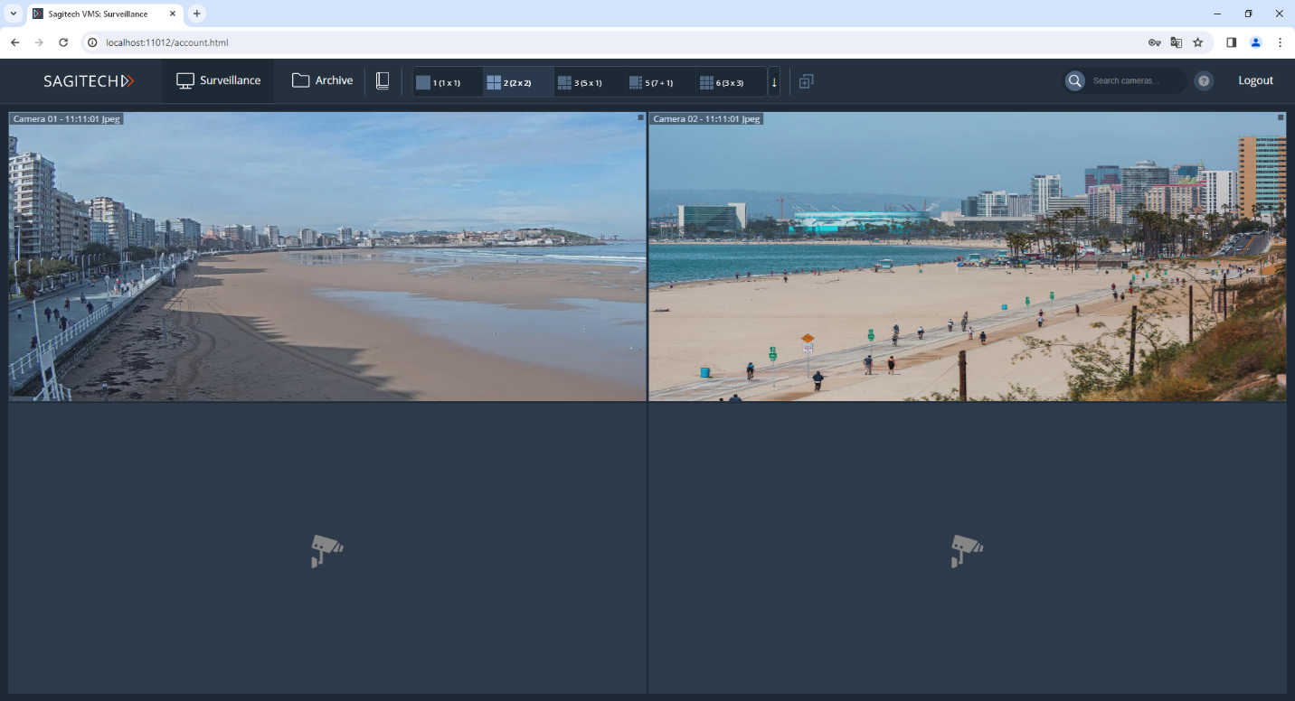
11.2 Surveillance mode
11.2.1 Setting up layouts
Layouts are available at the top of the screen. These layouts are not linked to the Sagitech Client.

To create your own layout, click on the icon
 .
.
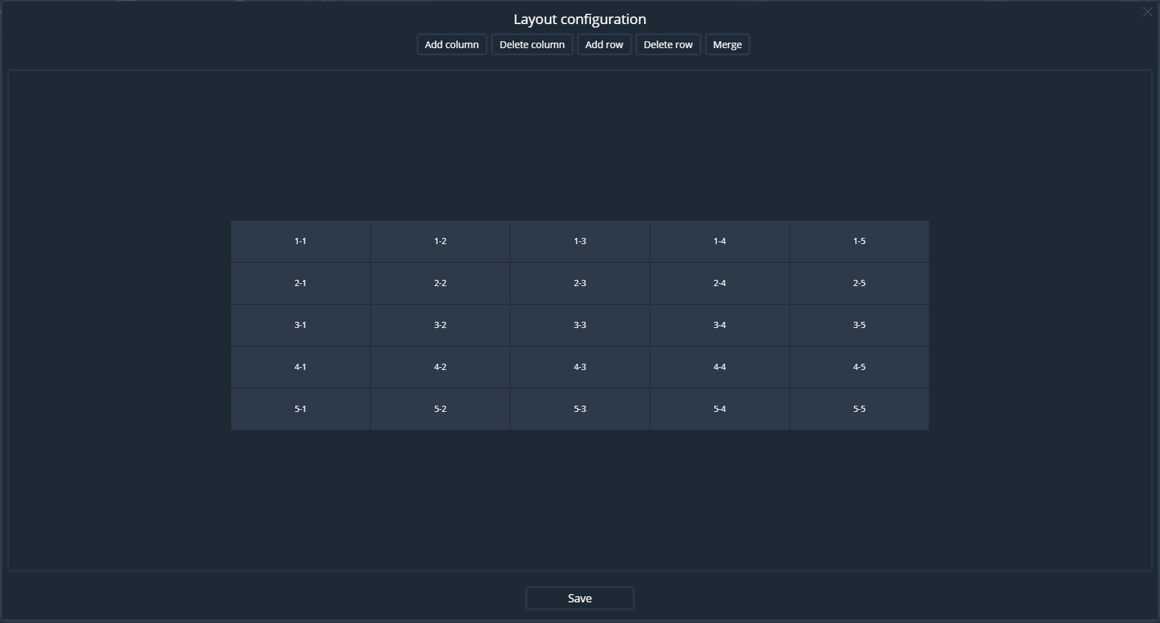
In the Layout addition window, you must select the number of rows and columns. By clicking on the LMB cells, the cell is selected for subsequent merging.

To merge the cells, click the "Merge" button.

After setting up the layout, click the "Save" button and set a unique layout name.
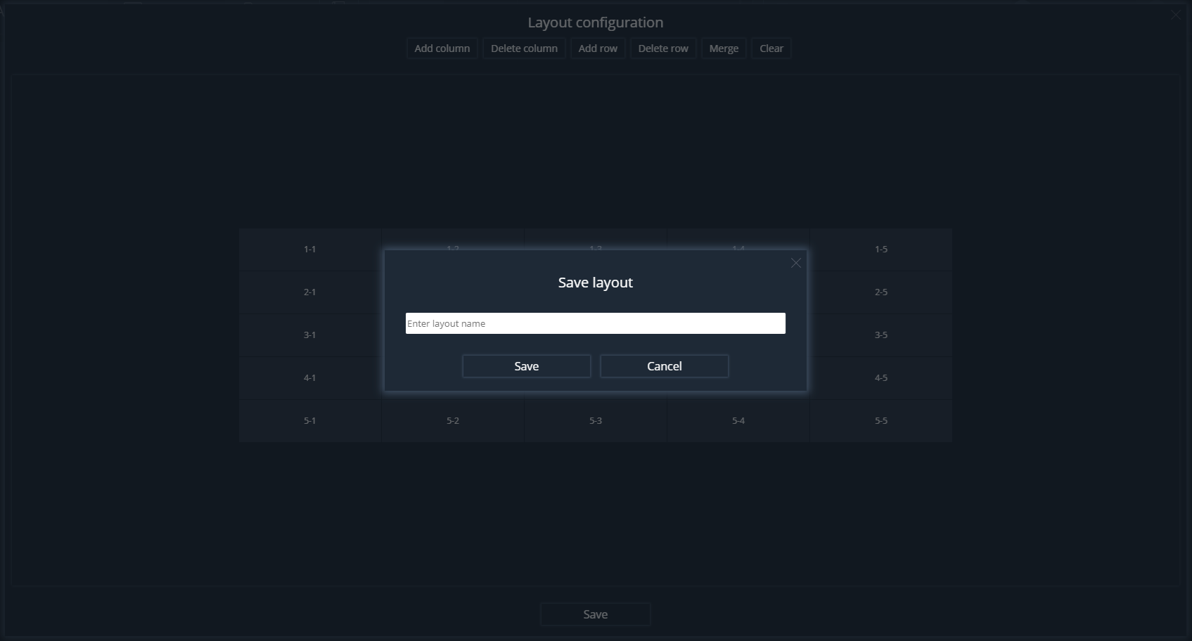
After saving the layout, it will appear in the top menu.

To delete a layout, click on the layout icon and select "Delete layout".
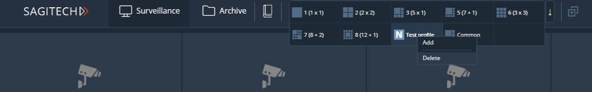
The general layouts are displayed after the user layouts and differ in
the type of icon. 
11.2.2 Setting up the camera display
To add a camera to a cell, select the LMB cell.

After selecting the cell, press the RMB and select "Choose camera".

In the camera selection window, select the camera and click Ok.

After confirmation, the video stream of this camera will be displayed in the cell.

The following actions are available in the context menu:
-
PTZ control.
-
Maximize/Minimize.
-
Choose camera.
-
Go to archive.
-
Save current frame.
-
Clear.
To expand the camera cell to full screen, use the appropriate item from the context menu or press Enter. A double-click reversal of the LMB is also available.
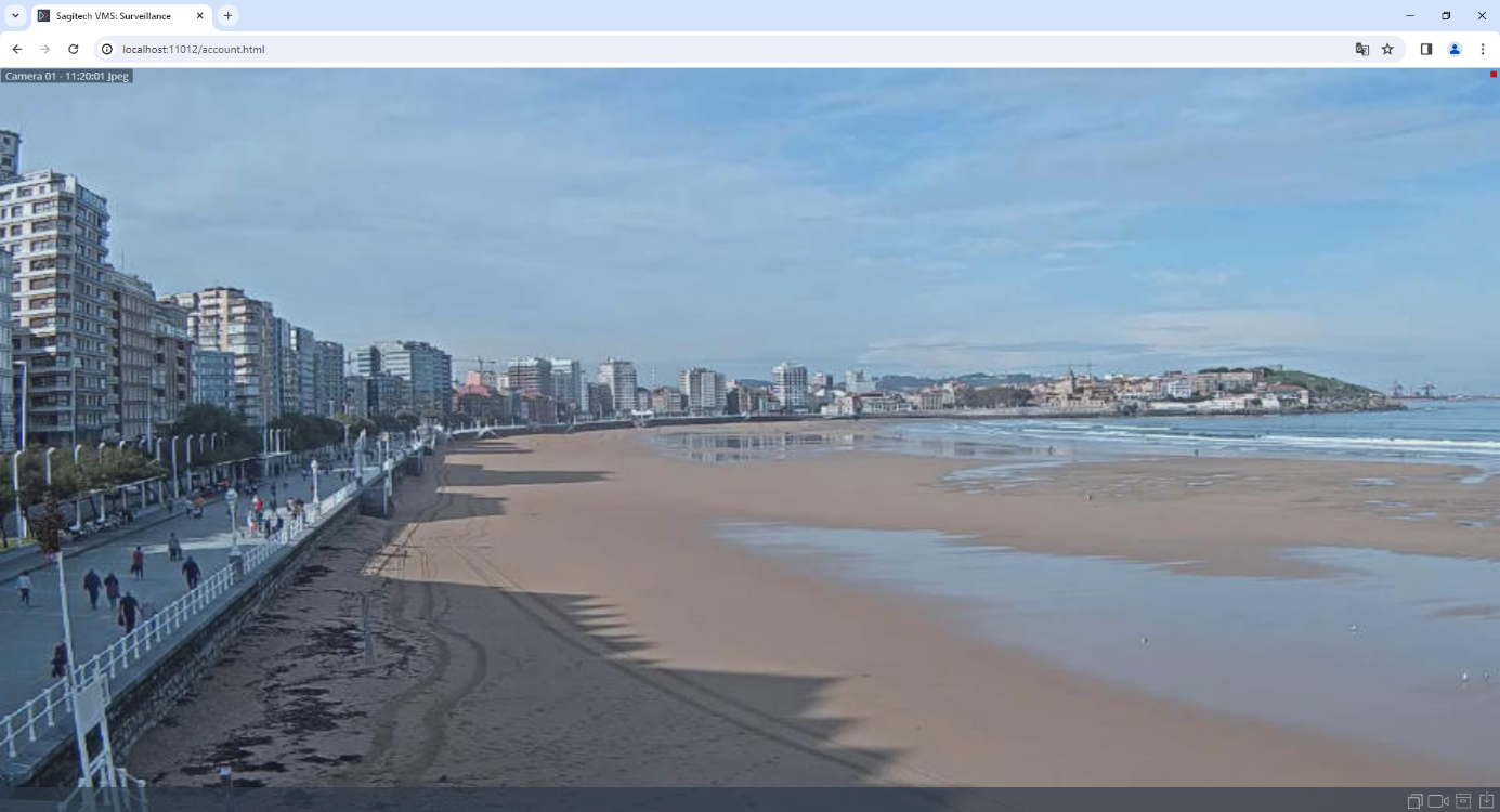
To collapse a cell, press the Escape or Enter key. You can also use a double click of the LMB or the corresponding context menu item.
You can use the arrow keys on your keyboard to navigate between cells.
Use the mouse wheel to digitally zoom in/out the image.

11.2.3 Quick action menu
For the convenience of users, when selecting a cell with a camera in the lower part, a window with icons opens, duplicating actions from the context menu.
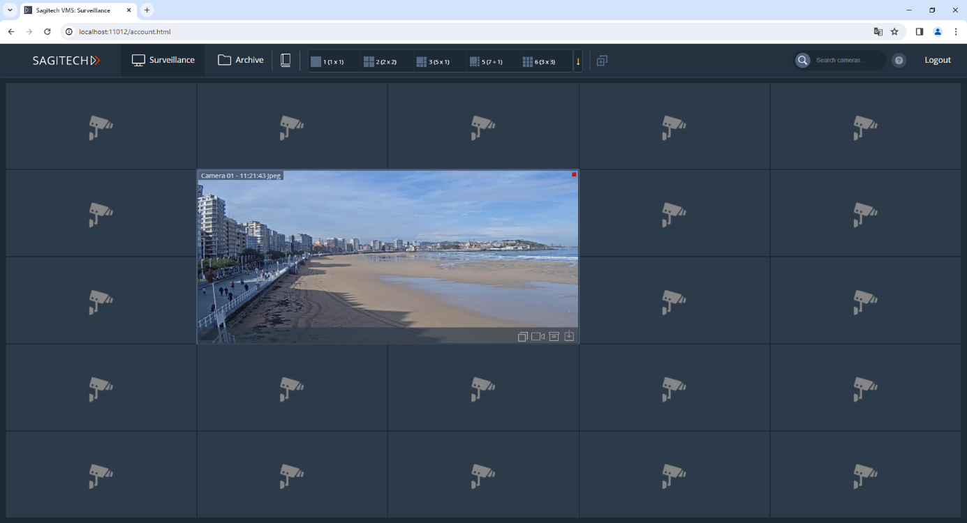
11.3 Archive mode
To switch to archive mode, select the archive link in the upper left part of the interface. The selection of the camera for viewing is carried out in the same way as the selection in the surveillance mode. The interface supports playback in forward and reverse directions at a given speed and switching to the required date and time.
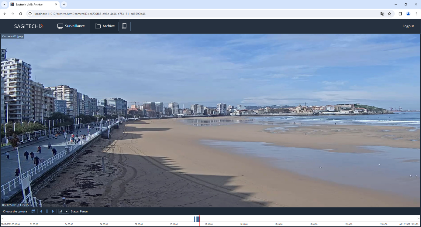
Archive export is available if the user has the appropriate rights in the "Configuration"-"Users" section.
Click on the RMB and select "Export video...".

Using the Archive export wizard, you can download videos in MP4 format.
11.4 Alarm journal
To switch to the alarm log, click on the icon
 in the upper left part of the
interface.
in the upper left part of the
interface.

To receive information about events, set the "Security mode" flag.
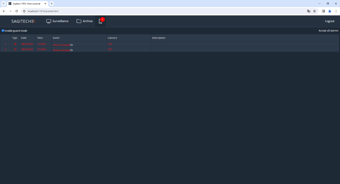
If you are in a different mode, for example, in observation, then new
events will be displayed in the upper corner of the icon

To confirm the event, click on a row in the table or the "Accept all alarms" button.

12 Controlling remote servers
12.1 Overview
The Sagitech VMS Server Control Utility allows to trace the relevant status of the set of remote Sagitech VMS servers. For every server the application provides the ability in real time to monitor its accessibility and the status of cameras: how many cameras are processed on the server, how many cameras are activated or deactivated, for how many cameras the recording is enabled and how many cameras are recording data to disks at the current moment.
The application can be started from the «Start» menu (Start->All programs-> Sagitech Video Management System -> Utilities -> Sagitech VMS Server control) (Fig. 11.1.1),
Fig. 11.1.1 Starting of Sagitech VMS Server control
12.2 Use
The main window of the application will appear on the screen after starting of Sagitech VMS Server Control (Fig. 11.2.1).
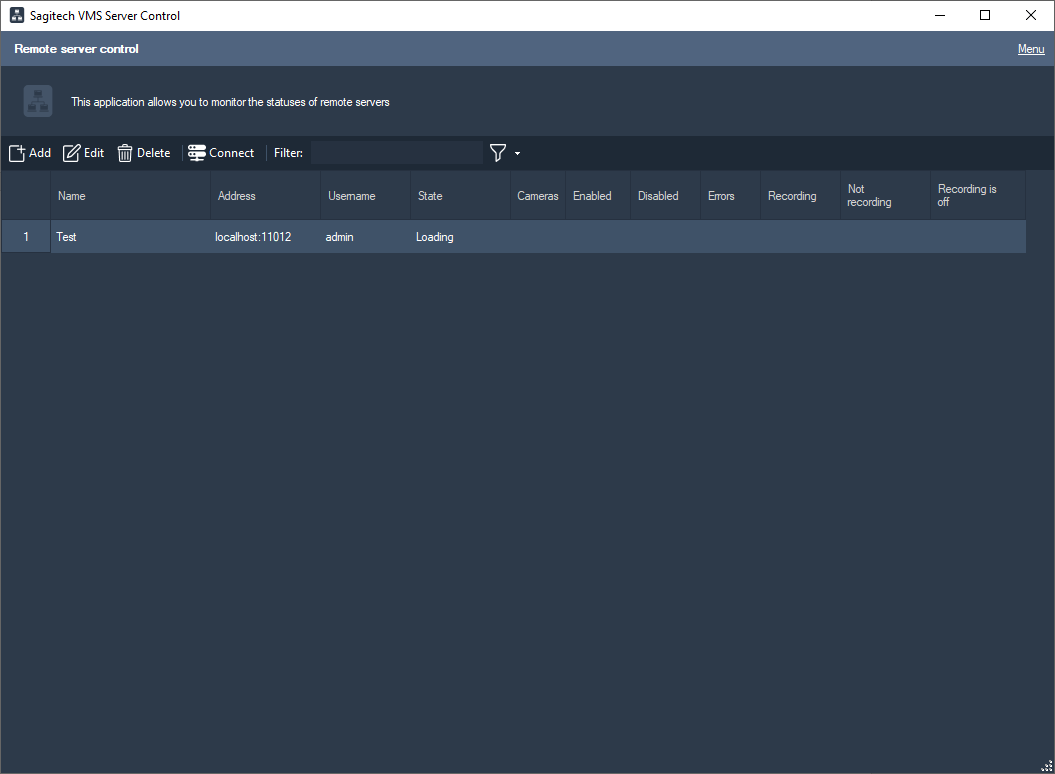
Fig. 11.2.1 The main window of Sagitech VMS Server Control
You can access the main menu with the help of the «Menu» hyperlink which is situated in the upper right part of the main window of the application. Aside from the main menu of the application the control elements are also available through a context menu, hot keys and a control panel (Table 11.2.1).
Table 11.2.1 The functional purpose of the elements of the menu of the video player.
| Location | Control element name | Purpose |
| Menu | Settings | It activates the window of the application settings. |
| Show specification | It displays an element of viewing a specification by the selected server. | |
| Display the log | It displays the event log of the application. | |
| About the program | It displays the information about the program. | |
| Exit | Exiting the application. | |
| Control panel and context menu | Add (Insert) | It adds a server to the list of controlled servers. |
| Edit (Enter) | It edits the parameters of the selected server. | |
| Delete (Delete) | It deletes the server from the list of controlled servers. | |
| Connect (Ctrl+Enter) | It connects to the selected server through the Sagitech VMS Client application. | |
| Filter (Ctrl+F) | It filters the list. |
After adding servers to the list of the controlled ones the application begins to send requests to each server. Requests are sent in intervals that are determined in the application settings ("Server request interval" setting). In the cycle of a request every server gets a specific status (by default «Unknown» status). If a server answers the request then the status of the cameras is displayed in the corresponding fields and the server gets the status "Ok" or "Error of cameras". If the status of a server cannot be obtained several times in succession then the server gets the "Unavailable" status. Every status is highlighted in a special color:
-
Unknown/Loading – black color
-
Ok - dark-green
-
Unavailable - red
-
Error of cameras – claret
Below there is a description of the columns that display information about the controlled servers:
-
Name – a line that is understandable to a user.
-
Address – a network address, or the domain name of the server (it is possible to specify the port number through a colon after the address, for example "server1:12345").
-
User – the name of a user on behalf of who the server is being connected to.
-
Status – one of the statuses of a server that are enumerated above.
-
Cameras – the total amount of cameras on a server.
-
Activated – the amount of activated cameras ("Deactivate the camera" is not checked in the camera settings in Sagitech VMS Client).
-
Deactivated - the amount of deactivated cameras ("Deactivate the camera" is checked in the camera settings in Sagitech VMS Client).
-
Errors – The amount of cameras that are currently inaccessible.
-
Recording is activated – the amount of activated cameras with enabled recording.
-
Recording is active – the amount of cameras with enabled recording that is being made at the moment.
-
Recording is inactive - the amount of cameras with enabled recording that is not being made at the moment (for example, when recording from a motion detector then this group will include cameras that have not detected any motion lately).
If necessary you can view detailed information about a server you are interested in – in order to do this it is necessary to activate the «Show details» option in the menu of the application. When the option is activated the main window of the program will be divided in two parts, and the server details will be displayed in the bottom part for the server that is selected in the upper part (Fig. 11.2.2).

Fig. 11.2.2 The main window with activated server details.