Extension modules
1 Introduction
1.1 Review
You can connect additional modules that allow you to expand the functionality of the video surveillance system in the professional edition of SagitechVMS.
The following modules are currently supported:
-
Sabotage detection module. Allows you to detect camera rotation, changing the field of view, overlapping the field of view with a foreign object, lighting and defocusing the camera.
-
Smoke detection module. Allows you to detect smoke in the frame.
-
Fire detection moddule. Allows you to detect fire in the frame.
-
Face detection module. Detects and selects faces from the video stream for subsequent search in the archive.
-
Abandoned object detection module. Detects abandoned items in the video stream and highlights them on the operator's screen.
-
License plate recognition module. Detects and recognizes car license plates in the video stream. Determines the direction of travel and the facts of entry/exit's. Allows you to maintain a database of numbers with the ability to link numbers to owners and combine them into groups. Allows you to intercept numbers from the list. Supports searching for numbers in the archive by attributes and exporting search results.
-
Module for loading events from the «ORION PRO». Allows you to get external events from Orion Pro and determine the responses of the video surveillance system in accordance with the configurable parameters.
-
Module for loading events from the «SIGUR». Allows you to get external events from Sigur and determine the responses of the video surveillance system in accordance with the configurable parameters.
-
Loud sound detection module. Allows you to detect the presence of a loud sound in the camera's audio stream and notify the operator about it.
- People counting module. Allows you to get and analyze data about the number of people who entered and left the controlled zone over a certain period of time.
-
Face recognition module. Detects and recognizes faces in the video stream. Allows you to maintain a database of employees with automatic face identification in real time, as well as the ability to split into groups (white and black lists). Supports searching the archive by a set of criteria.
-
Fisheye conversion module. Allows you to expand the round image obtained from the fisheye camera lens in one of three ways: 1x90 degrees, 2x180 degrees, and 4x90 degrees. Allows you to control the rotation angles and zoom with the virtual PTZ interface.
-
Tracking module. Monitors the movement of objects in the frame, making the construction of movement paths. Generates alarm events when an object crosses a specified line, moves in a certain zone, or stays in the specified zone for a long time.
1.2 General information about setup
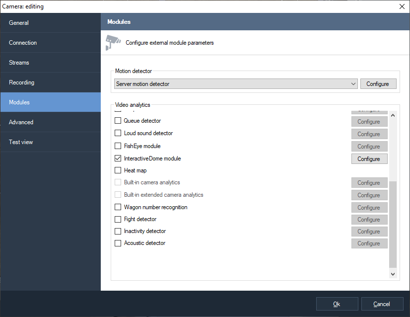
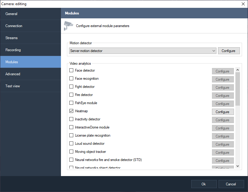
Enabling, disabling, and configuring modules is performed on the «Modules» tab of the camera settings window in the SagitechVMS Client application. Select the desired module and click the configure button to adjust its parameters.

Please note that the modules work in conjunction with the server motion detector, so the latter must also be enabled.
In the process, the module detects certain events. Each module has a default handling of the event associated with it. For example, if sabotage, smoke or fire is detected, an alarm will be generated, which will be transmitted to the security post, and information will be recorded in the archive of the video surveillance system.
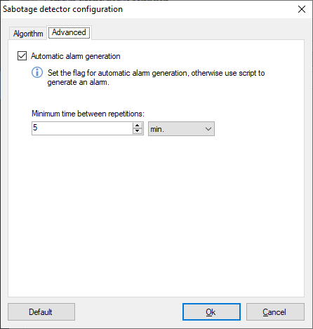
The figure above shows the window for configuring the parameters of the sabotage detector. Click the "Automatic alarm generation" just defines the default action is to generate anxiety. You can override the system's response to an event generated by the module by disabling this check box and creating a script to handle it.
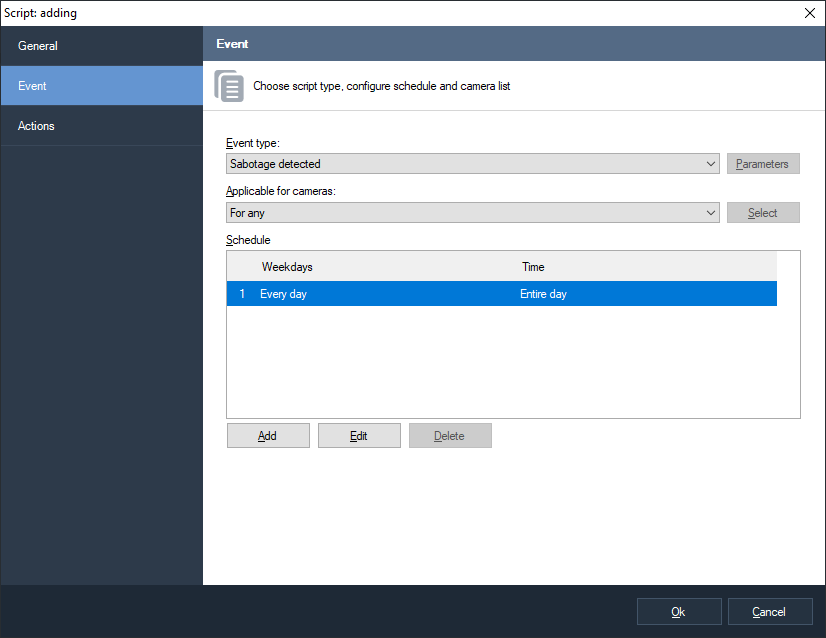
You can create a script in the Scripts section of the configuration section of SagitechVMS Client application. For example, the image below shows a script window that handles the "Sabotage detected" event. In addition to generating an alarm, an archive entry is also enabled and an email notification is sent to the specified address.
 |
 |
|---|---|
The default action for different modules may be different – this is not always an alert generation. For example, when a face is detected, it will be recorded with its coordinates and time stamp in the archive, as well as its illumination on the screen of the operator of the video surveillance system. For more information, please refer to the relevant section of this manual.
2 Sabotage detection module
The module is designed to detect the following events:
-
turning the camera
-
changing the camera's field of view
-
blocking the field of view with a foreign object
-
video camera illumination
-
the defocusing of the camera.
If one of these events is detected, the module generates an alarm that will be sent to the security post (the SagitechVMS Client application with the «Guard mode» enabled) and the information about it will be saved in the archive. You can set a minimum time interval after which a repeat alarm will be generated.
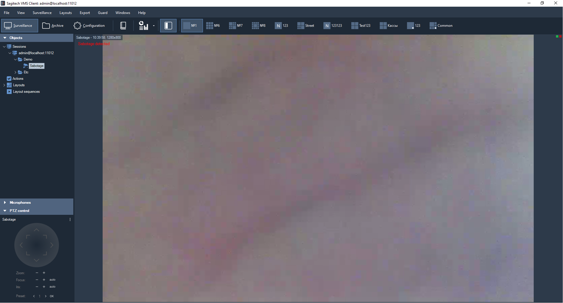
If you do not need to generate an alert, you can disable the corresponding flag. In this case, the message about sabotage will still be displayed on top of the camera's video stream in surveillance mode.
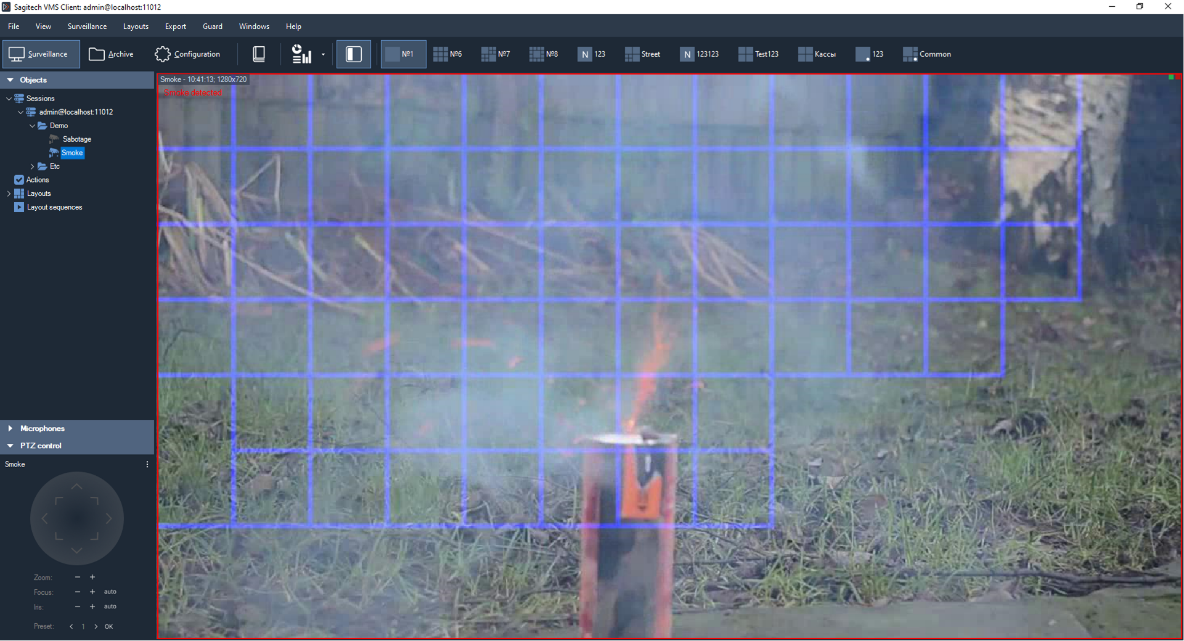
3 Smoke detection module
The module allows you to detect smoke in the frame.
When smoke is detected, the module generates an alarm that will be transmitted to the security post (the SagitechVMS Client application with the «Guard mode» enabled) and the information about it will be saved in the archive. You can set a minimum time interval after which a repeat alarm will be generated.
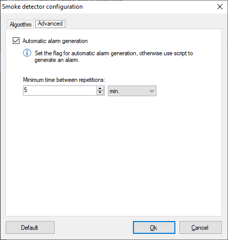
If you do not need to generate an alert, you can disable the corresponding flag. In this case, the message about smoke detection will still be displayed on top of the camera's video stream in surveillance mode.
4 Fire detection module
The module is designed to detect open fire in the camera's video stream.
When fire is detected, the module generates an alarm that will be transmitted to the security post (the SagitechVMS Client application with the «Guard mode» enabled) and the information about it will be saved in the archive. You can set a minimum time interval after which a repeat alarm will be generated.

If you do not need to generate an alert, you can disable the corresponding flag. In this case, the message about fire detection will still be displayed on top of the camera's video stream in surveillance mode.

5 Face detection module
The module automatically selects faces from the video stream, saving them to the archive for further selection.
Capabilities:
-
highlight detected faces with a color frame when viewing the camera's video stream in surveillance mode;
-
search and display on the screen all the faces detected over a certain period of time;
-
view video clips corresponding to the moment of face detection;
-
save a face image or an entire frame in JPEG format;
-
export the video fragment corresponding to the moment of face detection in AVI or RSVid format.
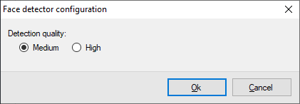
To enable the module, select the Face Detector flag on the modules tab of the camera settings window.

After that, the button for opening the module settings window will be available. In this window, you can set the desired quality of the module – medium or high. Average quality is set by default. When working in high-quality mode, the CPU resource consumption will be higher, but the number of detected faces will also increase.
Detected faces will be highlighted in the monitoring mode with a green border (the "Show analytics" option must be enabled for the video cell or the entire app).
To search for faces over a certain time interval, you must:
1) Switch to search mode (button
 on the toolbar of the SagitechVMS Client application);
2) Select the desired time interval;
3) If necessary, select the required cameras (by default, all cameras are searched);
4) Select «Object Search» mode (selected by default);
5) Select the event «Detected face» (set the Event option and open the
event selection window using the button
 ).
).
6) Click the «Search» button.
The detected faces will be displayed on the right side of the screen as a list of images. Select the desired face to quickly view the archive on the left side of the screen. Use the context menu to export the face image.

6 Abandoned object detection module
6.1 Review
Allows you to detect abandoned items in the camera's video stream.
A stationary object that is located in the surveillance zone longer than the interval set by the system administrator will be classified as an abandoned object. Information about it will be transmitted to the operators of the video surveillance system and stored in the archive for further search and analysis.
6.2 Module activation
To activate the module, follow these steps:
-
launch the SagitechVMS Client application;
-
go to the configuration tab;
-
select the "Cameras" section»;
-
in the "Cameras" section, select the desired camera and click «Edit»;
-
in the camera settings window that opens, go to the "Modules" tab;
-
enable and configure the abandoned object detector.

6.3 Configuring the module
In the settings of the detector of abandoned objects, there are two tabs "Algorithm" and "Advanced". In the "Algorithm" tab, we can adjust the sensitivity of the detector, set the detection time, and select the minimum and maximum size of the left object.

When an abandoned item is detected, the module generates an alarm that will be transmitted to the security post (the SagitechVMS Client application with the «Guard mode» enabled) and the information about it will be saved in the archive. You can set a minimum time interval after which a repeat alarm will be generated. This parameter can be set in the "Advanced" tab.

6.4 Surveillance
In surveillance mode, the module will signal the detection of an object by displaying a corresponding message on top of the displayed video. In this case, the item itself will be surrounded by a rectangle.

If you arm the camera (menu "Guard" - > "Guard mode", setting" Enable guard mode"), the alarm will be displayed when the detector is triggered. At the same time, if the video stream from the camera is currently displayed on the screen, the video cell with the left item will be circled by a red rectangle. If the video stream is not currently visible, a pop-up alert message will be displayed.
6.5 Search
To view the list of alarm situations that occurred during a certain time
interval, you need to use the search function in the archive. To perform
the search, switch to the same mode by selecting the menu item "View -
> Archive search", or use the icon on the toolbar
 .
Quick switch search mode on a particular camera is possible from the
surveillance mode and the view mode of the archive.
.
Quick switch search mode on a particular camera is possible from the
surveillance mode and the view mode of the archive.
To search for abandoned objects, you will need:
-
select the search time range – start/end date and time in the "Time interval" group fields;
-
select the required cameras: select the "Cameras" checkbox, go to the camera selection window (button to the right of the checkbox
),
select cameras in the tree list; -
select the "Events search" mode»;
-
select the "Events" checkbox, go to the event type selection window (the button to the right of the checkbox
),
and select the "Package detected" type in the window that appears; -
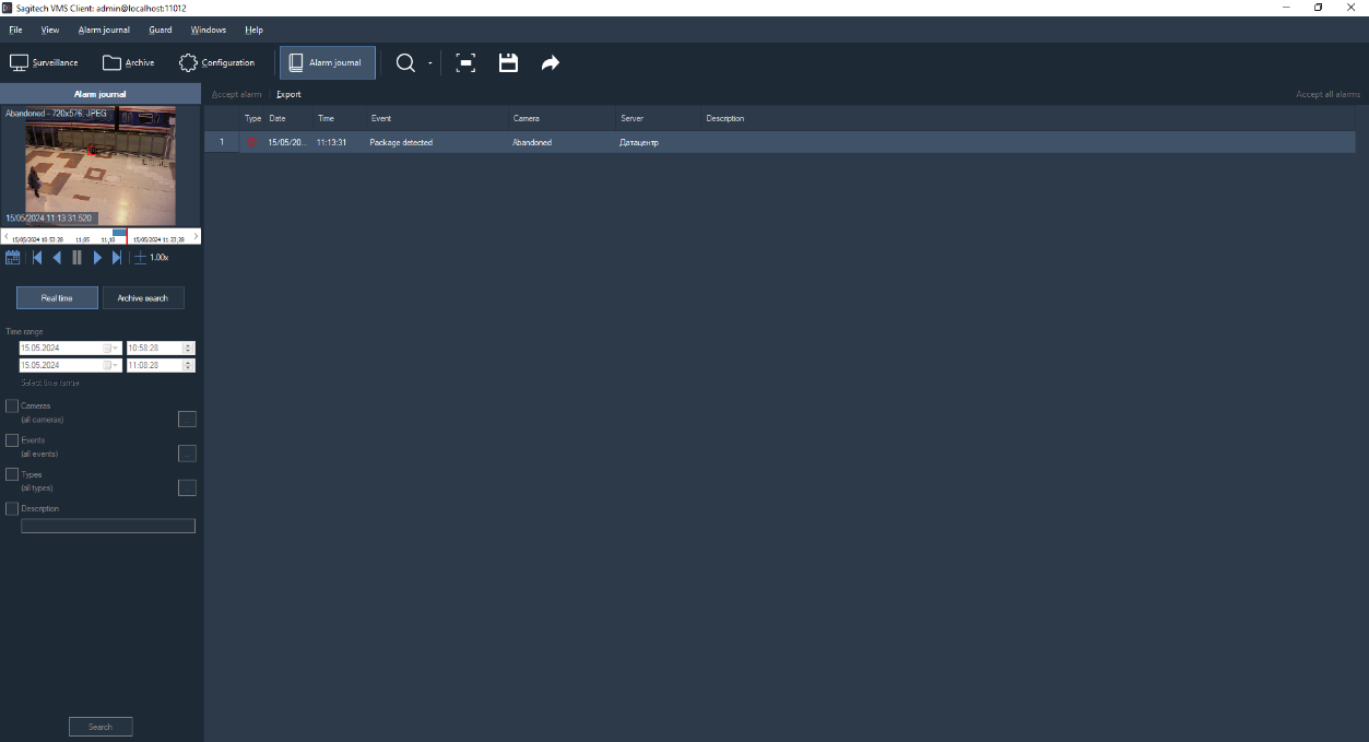
click the "Search" button.
A list of alarms with the "Package detected" type will be displayed in the right part of the search window.
7 License plate recognition module
7.1 Review
Functionality of the license plate recognition module (SagitechLPR):
-
detection of vehicles in the control zone, determining the direction of their movement and the fact of entry/exit's;
-
recognition of state vehicle registration plates;
-
saving information about passing cars to the archive, displaying information in real time;
-
search the archive for detected numbers by a set of attributes, upload the recognition history in CSV format;
-
maintaining a card index of vehicle numbers, with the ability to link additional fields to the number (information about the vehicle and its owner);
-
grouping number cards to create lists of interception, opening the barrier, and other automatic responses to the scenario;
-
management of a barrier;
-
getting data from the truck scales.
Module delivery modifications:
-
STD version-for car speeds up to 30 km / h (Parking, passageways, car washes, etc.), identification of numbers of one country from the support list, the ability to connect numbers of other countries.
-
Pro version-for car speeds up to 270 km / h (motorway), identification of numbers of one country from the support list, the ability to connect numbers of other countries.
Note
Note: the number of cameras that can be connected to a single compute and the supported countries are determined by the license.*
| Parameters | Note | Value |
|---|---|---|
| Number of connected cameras | according to the power of the PC | Up to 8 |
| Maximum allowed vehicle speed | depending on the license type | |
| STD – up to 30 km / h | ||
| PRO – up to 270 km / h. | ||
| The maximum horizontal angle for the camera | Up to 30 ° | |
| The maximum vertical angle for the camera | Up to 30 ° | |
| Automatic number recognition for 23 countries | Russia, Kazakhstan, Ukraine, Belarus, Moldova, Kyrgyzstan, Uzbekistan, Armenia, Abkhazia, Mongolia, the Netherlands, Poland, Belgium, Germany, Greece, Latvia, Hungary, Romania, Lithuania, Bulgaria, Estonia, the Czech Republic, Turkey, Italy, Israel, Finland, the Donetsk people's Republic, great Britain, Kyrgyzstan, Tajikistan; including special license plates — diplomatic, police, military, etc. | |
| Illumination in the control area | during the day under normal external conditions | illumination is not required |
| at night and twilight time of day | illumination of at least 100 Lux (IR illumination and halogen spotlights can be used) | |
| The probability of detecting | in the daytime | at least 95% |
| at night with artificial light at least 100 Lux | at least 92% | |
| The method of fixing the camera | on a support on the side of the road roads, on a farm above dear, in the car |
|
| Distance from the TV sensor to the control area | standard variant | 15-20 m |
| on customer request | depends on your choice video cameras and lenses |
|
| The height of the camera | possible height | 1-6 m |
| optimal | 3-4 m | |
| Depth of the control zone | for analog cameras | 5-7 m |
| for ip cameras | 7-10 m | |
| Width of the control zone | for analog cameras | 2.5-3 m |
| for ip cameras | 3-6 m | |
Quantity registration marks, recognized in the frame |
the first one is recognized number or all that found in the frame |
at least 1 |
The minimum set of technical means
-
CPU*:
-
Core i3 (Desktop 4 or higher):
-
up to 2 recognition channels at vehicle speeds up to 30 km / h;
-
up to 1 recognition channels at vehicle speeds up to 150 km / h;
-
Core i5 (Desktop 4 or higher):
-
up to 4 recognition channels at vehicle speeds up to 30 km / h;
-
up to 2 recognition channels at vehicle speeds up to 150 km / h;
-
up to 1 recognition channels at vehicle speeds up to 270 km / h;
-
Core i7 (Desktop 4 or higher):
-
up to 8 recognition channels at vehicle speeds up to 30 km / h;
-
up to 4 recognition channels at vehicle speeds up to 150 km / h;
-
up to 2 recognition channels at vehicle speeds up to 270 km / h;
-
-
RAM: 4 Gb or more.
-
Operating system:
-
Microsoft Windows 7/8/10 (32-edition (x86) or 64-edition (x64);
-
Windows Server 2008, 2012.
-
-
Monitor resolution: 1280x720 or more.
Note: the processor configurations for recognizing numbers with an image resolution of 1280x720 are shown.
Minimum set of software tools
The module requires the following software components installed on the PC:
-
SagitechVMS (at least 1.8.5);
-
Microsoft .Net Framework 4.5 Full;
-
Microsoft Visual C++ 2013 Redistributable x86;
-
Guardant security key.
7.2 Requirements for video cameras
-
Sensitivity is not worse than 0.01 Lux without taking into account the Sens-Up mode.
-
Possibility to set a fixed value of the electronic shutter (1/500 – for speeds up to 40 km / h, 1/1000 - up to 80 km / h, 1/2000 sec - up to 160 km / h).
-
Color cameras must have a full Day mode/Night with a removable IR cut-off filter.
-
ARD lens.
-
It is advisable to use cameras with an extended dynamic range (WDR-wide dynamic range).
The best recognition is achieved in a certain range of number sizes in the image:
Minimum size
width-80 pixels
the height is 18 pixels
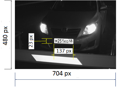

Recommended dimensions
width ~ 100 pixels
height ~ 22 pixels
Based on the fact that the number plate has a size of 520x112 mm, and the number image must be at least 80x18 pixels, it is easy to calculate the required resolution of the video camera (horizontally):
| Width of the control zone, mm | Horizontal resolution of the video camera, pixels | |
|---|---|---|
| Minimum | Recommended | |
| 2000 | 308 | 385 |
| 3000 | 462 | 578 |
| 5000 | 769 | 961 |
| 7000 | 1077 | 1346 |
As you can see, in most cases, the resolution up to 1280*720 is sufficient. There is no point in using higher-resolution cameras!
7.3 Requirements to the optical scheme
The correct choice of optical scheme significantly affects the quality of recognition! It is always very important to install and configure the TV cameras and lighting correctly before configuring the SOFTWARE. In the field of view of the camera should be part of the roadway on which cars pass in a straight line (without turns).
Requirements for camera tilt
-
vertical deviation of the camera axis no more than 30°
-
horizontal deviation of the camera axis is no more than 30°
-
horizontal deviation of the vehicle number image is no more than 15°


Parameters that affect the minimum distance from the camera support to the vehicle control zone:
-
Width of the control area
-
Height of the control area
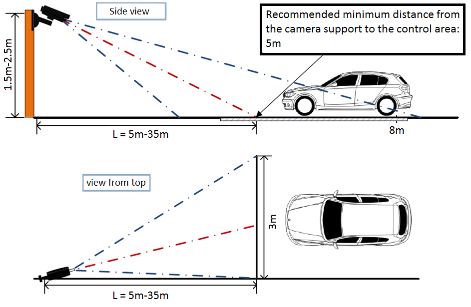
Selecting the focal length of the lens
- The width of the control zone is 3m
Matrix format 1/3”, video camera Resolution 640x480
| Distance to the control zone L, m | 5 | 10 | 15 | 20 | 25 | 30 | 35 |
|---|---|---|---|---|---|---|---|
| The focal length f, mm | 9 | 16 | 24 | 32 | 40 | 48 | 56 |
- The width of the control zone is 5m
Matrix format 1/3”, video camera Resolution 1280x720
| Distance to the control zone L, m | 8 | 15 | 20 | 25 | 30 | 35 | 40 | 45 | 50 |
|---|---|---|---|---|---|---|---|---|---|
| The focal length f, mm | 8 | 14 | 19 | 24 | 29 | 34 | 38 | 43 | 48 |
Configuring video cameras
-
The camera settings:
-
limit the exposure time (shutter speed, electronic shutter), or set a fixed value – 1/250, 1/500, 1/1000.
-
Turn on ARD.
-
Turn on WDR.
-
Adjusting the lens:
-
ARD, adjust the zoom and focus so that the car number in the image is the recommended size.
-
If there is insufficient light, use additional lighting.
7.4 Install the module
To use the license plate recognition module, you will need to install an additional distribution, which is located on the installation disk with the SagitechVMS system or on the official website of the product in the "Download" section
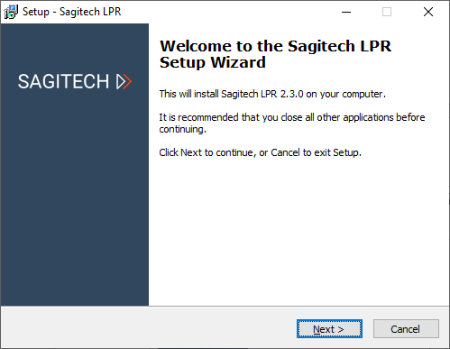
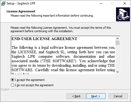
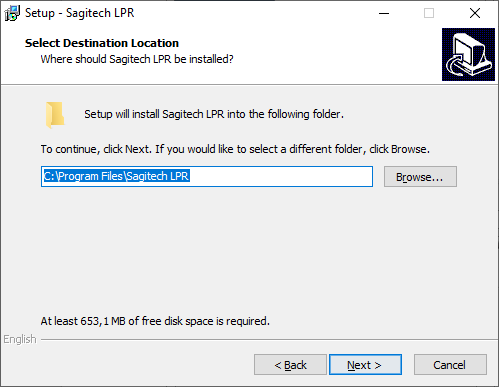
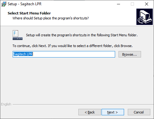
To begin the product installation, you must run the file SagitechLPRSetup.exe. After initializing the installation wizard, the installation wizard window appears. Go through all the steps of the wizard as shown in the pictures below.
 |
 |
|---|---|
 |
 |
 |
 |
The STD and PRO versions of the number recognition module are supplied with a license file (with the *.lic extension) and a USB security key. To activate the license, place the license file in the folder with the installed program (by default "C:\Program Files\SagitechLPR") and connect the security key to the USB port.
The LT version is delivered without the license file and security key. This edition is activated automatically when you activate the SagitechVMS software.
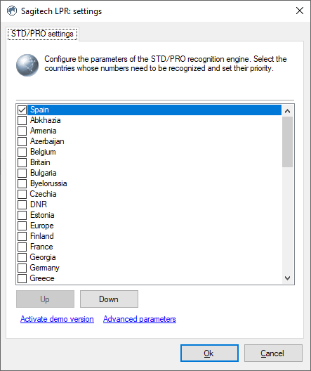
By default, the module will only recognize a number in Russian Federation. If your license supports recognition of other countries (the list of support includes 29 countries), you must switch the recognition parameters. To do this, launch the SagitechLPR application from the start menu and select the required countries in the window that appears.
 |
 |
|---|---|
After installing, activating, and configuring the recognition module, you must restart the server part of the SagitechVMS video surveillance system or restart the computer.
7.5 Parameter adjustment
To configure the module parameters, open the camera settings window, go to the "Modules" tab, and set the "License plate recognition module" flag.

The effectiveness of this module depends entirely on its parameters. Click the "Configure" button to display the settings window.
The main parameters of the module that affect the accuracy of determining numbers are located on the "Area and size" tab. Fine-tuning the area and size of the number will increase the speed of analysis, its accuracy, and reduce the load on the processor. Incorrect configuration can lead to missing analysis results, poor quality, or excessive load on PC resources.
The following parameters are available:
-
Recognition area size. This area defines the zone in which the search will be performed and recognition of license plates. We recommend limiting this area by excluding non-essential parts of the frame from analysis.
-
Minimum plate size. Allows you to set the minimum allowed number plate size. We recommend fine-tuning this parameter.
-
Maximum plate size. Allows you to set the maximum allowed number plate size. We recommend fine-tuning this parameter.
The "Freeze image" flag allows you to temporarily freeze the current frame. We recommend using this flag at least twice – to "catch" the car in the near and far points of the analysis (to fine-tune the minimum and maximum number sizes).

The «Algorithm» tab contains parameters for fine-tuning the algorithm.
7.5.1 Result forming
The recognition algorithm combines the recognition results from several consecutive frames and outputs the final result as the recognized number. These parameters allow you to configure the process of accepting the final result.
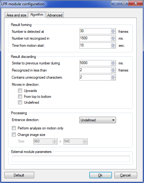
The final result is generated when any of the following conditions are met:
• Number is not recognized in.
If no numbers were recognized for the specified interval (in milliseconds) after the last recognition, the final result will be generated.
Changes between 1 and 99999 milliseconds.
Default: 500 ms.
• Number is detected at
If the number was recognized on the specified number of frames, the final result will be generated.
Changes between 1 and 100 frames.
Default: 30 frrames.
• Time from motion start
The final result will be generated no later than the specified time interval from the start of motion detection.
Changes between 1 and 600 seconds.
Deafult: 10 sec.
7.5.2 Result discarding
Do not include the number if at least one of the following conditions is met:
• Similar to previous number during.
If the number is recognized again within the specified time interval, it will not be counted. Allows you to avoid 'duplicating' numbers if the vehicle passes through the control zone for a long time.
Changes in limits from 0 up to 9999.9 milliseconds.
Default: 5000 ms.
• Recognized in less than
If the number is recognized less than the specified number of times, it will not be counted. The higher this value, the less likely it is that 'false' numbers will appear, but the greater the chance of missing the vehicle.
Changes between 1 and 50 frames.
Default: 2 frames.
• Contains unrecognized characters
If the number contains characters that could not be recognized and their number exceeds the specified number, it will not be counted.
Changes between 0 and 10 characters.
Default: 2.
• Moves in direction:
The image of the license plate moves along the frame in one of the directions while the vehicle is traveling. This is usually top-down or bottom-up. Algorithms, in most cases, allow you to determine the direction of movement and do not take into account the vehicle that is moving in the wrong direction.
• Upwards - ignore vehicles that move up and down the frame.
• From top to bottom - ignore vehicles that move from top to bottom in the frame.
• undefined - not take into account the vehicle, the direction of which has not been determined.
7.5.3 Processing
Sets additional processing parameters:
• Entrance direction
Allows you to associate the direction of movement of the car in the frame with the fact of entry or exit.
• Change image size
This option is necessary to reduce the resolution of the video stream coming to the module input in order to reduce the load on the processor and increase the speed of analysis. As a rule, it does not make sense to use a resolution greater than 1024x768.
7.5.4 External module parameters
Sets the path for connecting an external module (for example, integration with car scales).
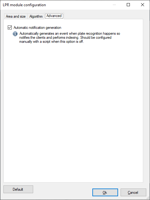
7.5.5 Advanced
If you disable the "Automatic notification generation" flag, the module will not generate events, and therefore they will have to be initiated by creating a scenario with the event type "car detected".
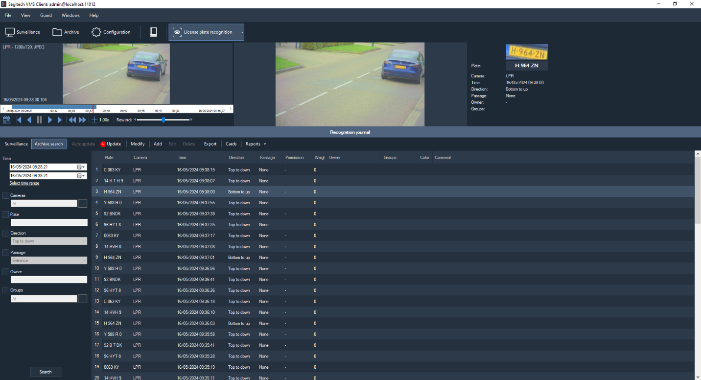
7.6 Interface
When viewing the video stream of a camera in surveillance mode with the license plate recognition module enabled in its settings, the recognized numbers will be displayed on top of the video surveillance cell. Output order: from left to right. Time to display the number on the screen: 15 seconds.

Data from all cameras that are used for number recognition can be
processed using the specialized "License plate recognition" mode, which
you can switch to using the button
 on the toolbar.

This mode has two modes-surveillance and archive search.
7.6.1 Surveillance mode
In this mode, all recognized numbers will be displayed as a list on the screen in order of priority.
The video stream of the camera will be displayed in the upper – left part of the screen (there are two possible modes: displaying the video stream of the specified camera, or displaying the video stream of the camera for which the last number was recognized). To the right of the video stream, a frame corresponding to the selected event and information about it is displayed.
The recognition log is located below. When the "auto-Update" button is enabled, all events that occur will be automatically displayed in the log. When selecting a record manually, this flag is reset. In this case, the number of missed events will be displayed as their number to the right of the "Update" button (see the figure below).

You can add the number highlighted in the log to the card file, edit or delete the card. It is also possible to export the displayed list to a CSV / Excel file.
7.6.2 Archive search mode
This mode allows you to download the history of number recognition from the archive of the video surveillance system. Set the parameters you are interested in and click the "Search"button.
In this mode, you can also manage your card files and export them to a CSV/Excel file.
7.6.3 Export
Export allows you to save the entries displayed in the recognition log to a user-defined file.

Select the columns you want to export and click «Export».
7.6.4 Cards
The card library allows you to create and manage car cards-objects that contain additional information about the car, its owner, and group membership. You can go to the card library using the "Cards" button, which is available from both sub-modes.
The "Import" and "Export" buttons allow you to load the card file from a file in CSV format, or upload the card file to a file. The following conditions must be met:
-
Each line of the file contains information about a single card.
-
Fields in the line are separated by semicolons.
-
Column order: plate; model; name; work place, position, phone, groups.

The window for adding / changing the owner's card is shown in the figure below.

The "Groups" field allows you to assign a car to one or more groups. Depending on the group, you can configure the behavioral response of the system. For example, you can create a scenario that will generate an alert when a car belonging to the "Black list" group is detected in the video stream, or, conversely, automatically open the barrier when a car is detected that is included in the white list.
The window for editing the list of groups is shown in the figure below.

The pass field allows you to open the pass editing window– which is a set of rules according to which a decision on an entry permit will be formed.

-
Period – allows you to limit the period during which the entry of the car is possible. If the period is not specified, the restrictions do not apply.
-
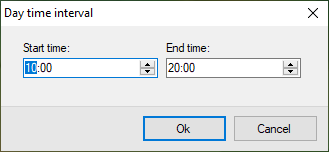
Access time – allows you to limit the time during which entry is possible on a daily basis. If not specified, restrictions do not apply.
-
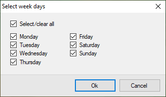
Access days – allows you to set the days of the week for which entry is allowed.
-
Access by maximum number of cars of the same group on the territory – allows you to prohibit the entry of cars into the territory if there is already a specified number of cars in the same groups as the current one. If the current car belongs to several groups, then the data for the groups are summed up. For this parameter to work correctly, it is necessary that the "Count cars on the territory" flag is enabled in the settings of the auto number recognition module.
-
Comment – allows you to set an arbitrary custom description of the "Pass" object.
7.6.5 Reports
The information on the passes is displayed in the card file window. There are 3 types of reports available:
-
«Cars inside»
-
«Entrance and exit»
-
«Parking time violation»
Passes with expired validity period are highlighted in red. Passes whose validity period has not yet come will be marked in blue. Passes whose validity period has already come will be highlighted in green.
The result of the pass check is the value of the "Entry Permit" property linked to the event of the car's passage. The behavior required by the user is formed using scripts. For example, if it is necessary to open a barrier for those cars whose passage was allowed, it is necessary to create a scenario for processing the event "License plate detected". Scripts are configured on the "Scripts" tab of the "Configuration" mode.

When editing the script, click the "Parameters" button to the right of the event type selection field. In the window that appears, you need to configure the value of the "Passage permission" field necessary for the scenario to be triggered.

Next, on the «Actions» tab of the script settings window, you need to configure the commands for opening the barrier.

8 Module for loading events from the Sigur (Sphinx)
8.1 Review
SagitechVMS supports the ability to get external events from the SIGUR and determine the responses of the video surveillance system in accordance with configurable parameters.
8.2 Configuring data loading
Interaction with the Sigur system takes place over the network using a special OIF integration Protocol. When you start the Sigur server, a TCP server is created, waiting for connections on the port defined by the “OIF 1_Port" parameter in the server process configuration file "sphinxd.cfg". By default, port 3312 is used.
To enable receiving events on the SagitechVMS side, you will need to configure the configuration file "C:\Program Files\SagitechVMS\config\Sigur.config", namely, define the following parameters:
-
serverName – the domain name of the ACS server, or its IP address
-
serverPort – OIF-port of ACS (default: 3312)
-
userName – user name of the ACS (e.g., Administrator)
-
password – password of the ACS user
An example of configuring the configuration file in accordance with the previously obtained parameters is shown in the figure below.

Attention! After editing and saving this configuration file, you will need to restart the server part of the SagitechVMS.
You can check the correct operation of the module using the "SagitechVMS server event Log" application. If there are configuration errors, immediately after starting the server part, the log will display the message "Error loading data" with the source "Sigur". This event will be repeated at intervals of several minutes (see the figure below).
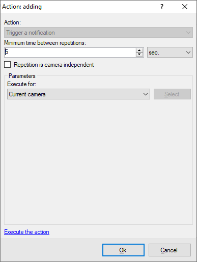
8.3 Configuring the system response
In response to events received from Sigur, it is possible to set behavioral responses in the SagitechVMS System. The following actions are supported:
-
Send SMS
-
Send Email
-
Run application at server
-
Execute HTTP request
-
Start record
-
Stop record
-
Trigger an alarm
-
Trigger a notification
-
Save frame to disk
-
Disable frame skipping while recording
To configure reactions, you must:
-
Connect to the video surveillance server using the SagitechVMS Client application.
-
Go to the Configuration section, Scripts subsection.
-
Click the "Add" button.

-
On the General tab of the script add window, set the script name.
-
On the "Event" tab, select the event type "Sigur event".
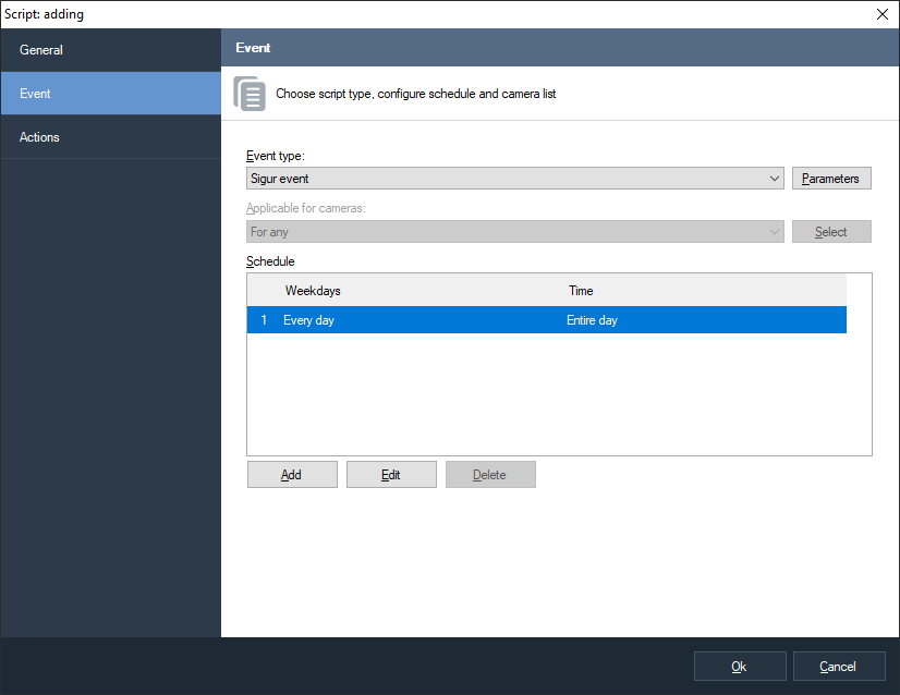
-
Open the event settings window by clicking the "Parameters" button to the right of the "Event type" field.
-
In the settings window that appears, click the Add button to add a new event parameter.

-
In the parameter editing window, select the desired parameter, comparison type, and set the value.
-
Save the parameter by clicking OK.
-
Repeat the operation of adding the parameter if necessary. Note that when adding several parameters of the same name, they are combined using the or condition, and when setting parameters with different names, they are combined using the and condition.
-
Save the list of parameters by clicking «OK».
-
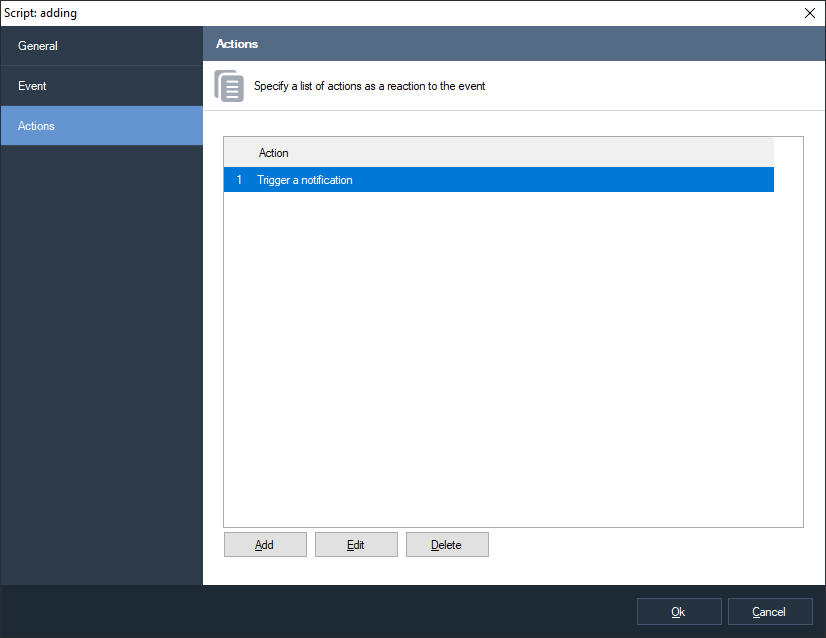
Set the necessary actions on the Actions tab of the script add window. For example, you can trigger an alarm for the camera closest to the event point.
- After completing the configuration, click OK in the add script window to save the data.
9 Loud sound detection module
The module allows you to detect the fact that the user-defined volume threshold has been exceeded in the camera's audio stream and notify the operator about it.
Set the required trigger threshold in the module settings on the «Detection parameters» tab. The «Current level» parameter displays the sound level at the current time.
If a loud sound is detected, the module generates an alarm that will be transmitted to the security post (the Sagitech VMS Client application with the Security mode enabled) and the information about it will be saved in the archive.
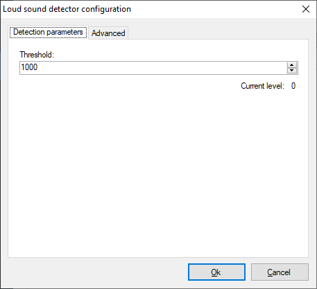
You can set the minimum time interval after which a repeat alarm will be generated on the «Advanced» tab. If you do not need to generate an alert, you can disable the corresponding flag. However, a message about a loud sound will still be displayed on top of the camera's video stream in surveillance mode.

10 People counting module
10.1 Review
Capabilities:
-
receive and analyze data on the number of people entering and exiting the controlled zone over a certain period of time;
-
evaluate the passability and efficiency of the staff.
10.2 Requirements to the optical scheme
The following conditions are required for the module to work correctly:
-
The camera must be positioned vertically above the counting area;
-
The size of the person in the frame should not exceed 30% of the frame area;
-
The frame rate must be at least 5 frames / sec.
10.3 Parameter adjustment
To configure the module parameters, open the camera settings window, go to the «Modules» tab, and set the «People counter» flag.

Click the "Configure" button to display the settings window.
The main parameters of the module that affect the accuracy of user counting are located in the "Algorithm" tab. Fine-tuning the input direction, the coordinates of the counting area, and the size of the person will reduce the load on the processor and increase the accuracy of the count. Incorrect settings can lead to missing analysis results and poor quality.
The following parameters are available:
-
Entrance direction. This parameter determines the direction of movement of people crossing the counting area.
-
Person’s size. Allows you to set the maximum allowed size of a person.
The "Freeze image" flag allows you to temporarily freeze the current frame. We recommend using this flag at least twice – to "catch" a person passing through the counting area (to fine-tune the coordinates of the counting area and the size of the person).

10.4 Interface

Data from all cameras where users are counted can be processed using the
specialized "People counter" mode, which you can switch to using the
button
 on the toolbar.
10.5 Building reports
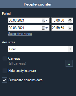
The following parameters are available:
-
From. This parameter defines the date and time from which the calculation starts.
-
To. This parameter defines the date and time when the calculation ends.
-
Axis sizes. This parameter defines the counting interval to be specified on the X-axis.
-
Hide empty intervals. This parameter allows you not to display empty intervals before the first non-zero value and after the last one.
-
Cameras. This parameter allows you to select cameras that use the user counting module to plot graphs for multiple cameras at once.
-
Summarize cameras data. This parameter allows you to sum the counter values for the selected cameras.
Capabilites:
-
Autosize. This button allows you to scale all the counter values.
-
Export. This button allows you to export graphs in .pdf format (table view) and Excel format (table + graph).

When you hover the mouse cursor, you can get information about the camera, time, and counter value.
11 Queue detector
11.1 Review
Module functionality:
-
receive and analyze data on the number of people in queues in controlled areas for a certain period of time;
-
evaluate the patency and efficiency of the staff.
11.2 Requirements to the optical scheme
The following conditions are required for the module to work correctly:
-
The camera must be fixed.
-
The camera angle should be in the range of 30 to 60 degrees to the vertical.
11.3 Parameter adjustment
To configure the module parameters, open the camera settings window, go to the modules tab and set the queue detector flag.

Click the "Configure" button to display the settings window.
The main parameters of the module that affect the accuracy of counting visitors are located in the "Algorithm Parameters" tab. Incorrect settings can lead to missing analysis results and poor quality.
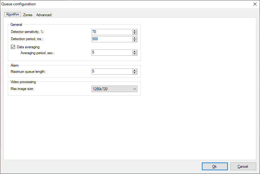
The following options are available:
-
Detector sensitivity. If the module does not detect people in a given area well, it is worth increasing the sensitivity. If the module takes extraneous objects for people, it is worth reducing the sensitivity.
-
Detection period. Minimum time to identify a person in the zone.
-
Data averaging. Allows you to make queue detection more resistant to sudden changes in the number of people in the zone.
-
Maximum queue length. When the number of people in the zone exceeds this number, an alarm will be generated.
-
Video processing. The higher the resolution, the more accurate the detection will be, but the load will increase.
On the "Zones" tab, you can manage detection zones.

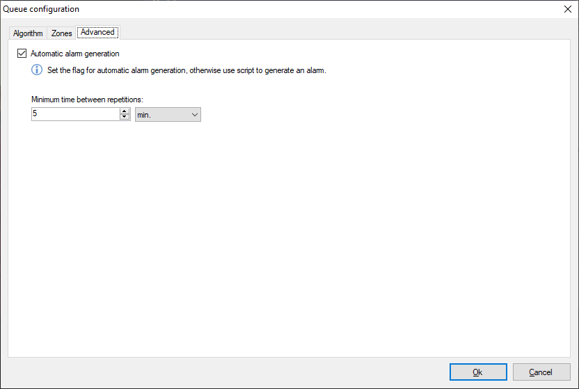
On the "Advanced" tab, you can configure the alarm generation parameters.
11.4 Interface
In the "Surveillance" mode, queue data is displayed in the upper right corner of the video stream.

Data from all cameras where visitors are counted can be processed using
a specialized "Queue module" mode, which can be switched to using the
button
 on the toolbar.

11.5 Building reports

The following options are available:
-
From. This parameter defines the date and time from which the calculation starts.
-
To. This parameter defines the date and time when the calculation ends.
-
Axis sizes. This parameter defines the counting interval to be specified on the X-axis.
-
Hide empty intervals. This parameter allows you not to display empty intervals before the first non-zero value and after the last one.
-
Cameras. This parameter allows you to select cameras that use the queue detector module to plot graphs for multiple cameras at once.
-
Summarize cameras data. This parameter allows you to sum the counter values for the selected cameras.

The functionality of the buttons:
-
Autosize. This button allows you to scale all the counter values.
-
Export. This button allows you to export graphs in .pdf format (tabular view) and in Excel format (table + graph).
When you hover the mouse cursor over the graph, you can get information about the camera, time, and the value of the counter.
12 Face recognition module (Sagitech FR)
12.1 Review
Capabilities:
-
detection of persons in the control area;
-
saving information about face detection to the archive, displaying information in real time;
-
search the archive for detected faces by a set of features, upload the recognition history in CSV format;
-
maintaining a card file of individuals with the ability to link additional fields (information about individuals individual);
-
grouping of face cards to create black / white lists and other automatic reactions according to the scenario.
Note: the number of cameras that can be connected to a single computer is determined by the license.
Minimum set of software tools
The module requires the following software components installed on the PC:
-
SagitechVMS (version 1.9.0 or higher);
-
Microsoft .Net Framework 4.5 Full;
-
Microsoft Visual C++ 2015 Redistributable x86;
-
HASP security key driver.
12.2 System requirements
12.2.1 CPU mode
When using the face recognition module in CPU execution mode, the following resources are required (for analyzing a 1920×1080 H.264 video stream):
- CPU: ~1.5 Intel processor cores at 2 GHz or higher with AVX2 support
- RAM: ~2 GB of memory
- The specified requirements are per processed video stream
The load estimation is based on the following conditions:
- A database of up to 100,000 faces
- Up to one new face per second appearing in the camera’s field of view (the number of faces simultaneously present in the frame may be higher).
12.2.2 GPU mode
To use GPU acceleration mode, an NVIDIA graphics card with CUDA support is required.
Supported GPU architectures:
- Turing
- Ampere
- Ada Lovelace
- Hopper
- Blackwell
The release uses CUDA 12.9. Support for graphics cards based on newer architectures may be limited or unavailable.
Minimum NVIDIA driver versions:
- Linux: 525.60.13 or higher
- Windows: 528.33 or higher.
12.3 Requirements to the optical scheme
The correct choice of optical scheme significantly affects the quality of recognition! It is always very important to install and configure cameras and lighting correctly before configuring the software.
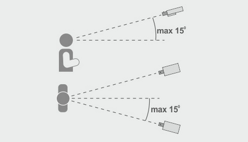
Requirements for the location of the cameras
-
Optimal camera position – the camera is aimed at the person's face;
-
The recommended horizontal deviation of the camera axis is no more than 15°;
-
The recommended vertical deviation of the camera axis is no more than 15°.
Minimum image requirements for identification
-
Recommended pupil distance is 60 pixels;
-
Minimum face size 64 x 64 pixels;
Configuring video cameras
-
The camera settings:
-
You must limit the exposure time (shutter speed, electronic shutter) or set a fixed value - from 1/100 to 1/250;
-
Adjusting the lens:
-
To configure ARD to adjust zoom and focus so that the person in the picture was not blurry and you can see the texture of the face;
-
If there is insufficient light, use additional lighting.
12.4 Install the module
To install the face recognition module, follow these steps:
-
Launch the distribution file. There are two versions of the distribution – demo and license. In the case of a demo version, its name contains the suffix "- demo", for example, "SagitechFRSetup-1.9.0.exe".
-
In the installation wizard window that opens, click "Next" and follow the steps of the installation wizard.
After completing the installation, activation, and configuration of the facial recognition module, you must restart the server part of the SagitechVMS video surveillance system or restart your computer.
12.5 Parameter adjustment
To configure the module parameters, open the camera settings window, go to the "Modules" tab, and set the "Face recognition" flag.

The effectiveness of this module depends entirely on its parameters. Click the "Configure" button to display the settings window.
The main parameters of the module that affect the accuracy of face detection are located in the "Area" tab. Fine-tuning the area and size of the face will increase the speed of analysis, its accuracy and reduce the load on the processor. Incorrect configuration can lead to missing analysis results, poor quality, or excessive load on PC resources.
The following parameters are available:
-
Recognition area size. This area defines the area where face search and recognition will be performed. We recommend limiting this area by excluding non-essential parts of the frame from analysis.
-
Min face size. Allows you to set the minimum allowed face size. We recommend fine-tuning this parameter.
-
Max face size. Allows you to set the maximum allowed face size. We recommend fine-tuning this parameter.
The "Freeze image" flag allows you to temporarily freeze the current frame. It is recommended to use this flag at least twice – to "catch" the face in the near and far points of the analysis (to fine-tune the minimum and maximum face sizes).

The "Algorithm" tab contains parameters for fine-tuning the algorithm.
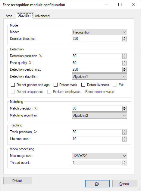
12.5.1 Mode
• Mode
Default: Recognition
allows you to select the module operation mode (detection, verification, analytics or recognition).
• Decision time, ms.
Default: 750 ms.
This parameter allows you to configure the time period during which images of the same person's faces will be accumulated in order to select the face with the highest quality.
12.5.2 Detection
These parameters allow you to configure the face detection process.
• Detection precision, %
Default: 80%
The higher the value of this parameter, the more accurate the object will be defined as a face. If the values are low, the probability of identifying another object as a person increases.
• Face quality, %
Default: 60%
This parameter allows you to flexibly configure the quality threshold of the detected face. The higher the value of this parameter, the higher the probability of detecting a particular face, but the greater the probability of missing faces. If the value of this parameter is low, false positives may occur.
• Detection period, ms.
Default: 250 ms.
The time interval that determines the frequency of searching for new faces in the video stream. The higher the frequency of detection, but also the greater the load on the processor.
• Detection algorithm
Allows you to select the most appropriate detection algorithm for the conditions (a set of functions that are used to detect faces in the video). An algorithm with a lower number has higher performance due to a slight decrease in accuracy. If the selected settings do not detect faces, select a different algorithm.
• Detect gender and age
Default: false.
Allows you to enable gender and age detection.
12.5.3 Matching
This parameter allows you to configure the accuracy of facial recognition.
• Match precision, %
Default: 80%.
It allows you to set the required accuracy of facial recognition (accuracy of comparison with the face in the file). If the comparison results are lower than the specified value, the person is identified as unrecognized.
• Matching algorithm
Allows you to select the most appropriate recognition algorithm for the conditions (a set of functions that are used to compare faces in the video). An algorithm with a lower number has higher performance due to a slight decrease in accuracy. If faces are not recognized as a result of the selected settings, select a different algorithm.
12.5.4 Tracking
These parameters allow you to configure the accuracy of tracking.
• Track precision, %
Default: 80%
This parameter allows you to set the required accuracy for combining faces. The higher the accuracy of the comparison with the standard, the less likely it is that the result is incorrect, but this may lead to missing some of the faces.
• Life time, sec.
Default: 10 sec.
This parameter sets the period for merging the recognized face. When this parameter is increased, the probability of multiple identification of the same person who has been in the frame for a long time decreases.
12.5.5 Video processing
These parameters allow you to configure video stream processing.
• Max image size, %
Default: 1280х720
Allows you to compress the image coming from the camera before analyzing it. A lower resolution means less CPU load, and a higher resolution means higher recognition accuracy.
• Thread count
Default: 1
Defines the number of processor cores that are used simultaneously when analyzing a single video stream. In most cases, we recommend leaving this default value.
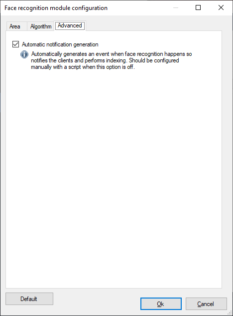
12.5.6 Advanced
If you disable the "Automatic notification generation" flag, the module will not generate events, and therefore they will have to be initiated by creating a script with the "Face recognized" event type.
12.6 Interface
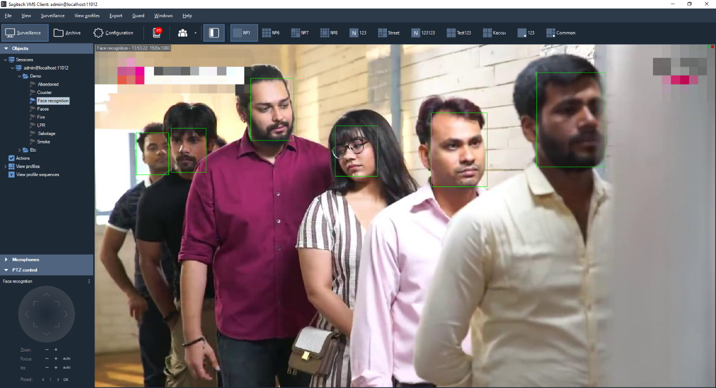
Data from all cameras that are used for facial recognition can be
processed using the specialized "Face recognition" mode, which you can
switch to using the button
 on the toolbar.

This mode has two modes: surveillance and archive search.
12.6.1 «Surveillance» mode
In this mode, all recognized faces will be displayed as a list on the screen in order of priority.
The right side of the screen will display the video stream from the camera (possibly two modes – displays video stream of a given camera or the display video camera for which it was recognized last person). A frame corresponding to the selected event, the person's face, and information about it is displayed at the bottom of the video stream.
When the "Autoupdate" button is enabled, all events that occur will be automatically displayed in the log. When selecting a record manually, this flag is reset. In this case, the number of missed events will be displayed as their number to the right of the "Update" button (see the figure below).

You can add a person selected in the log to the card file, edit or delete the card. It is also possible to export the displayed list to a CSV/Excel file.
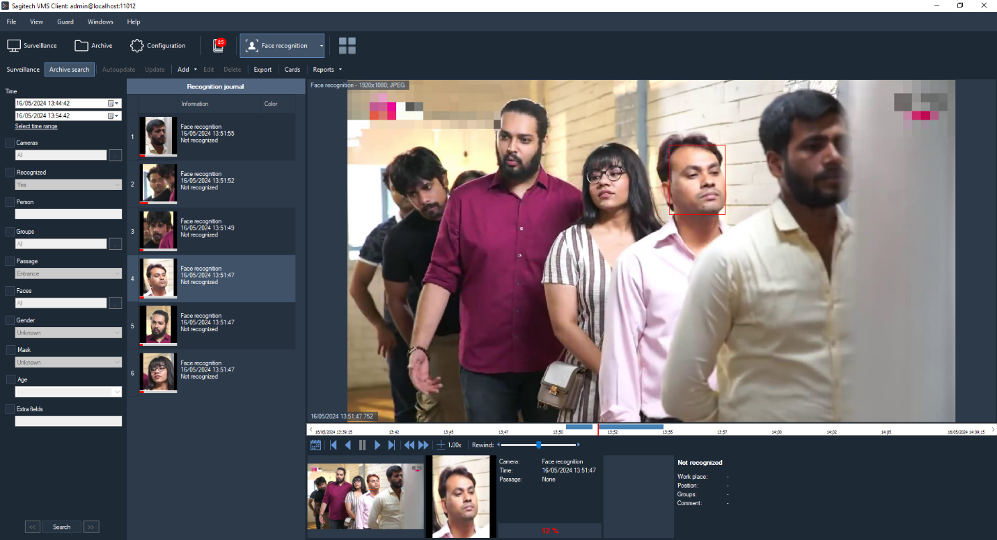
12.6.2 «Archive search» mode
This mode allows you to download the history of facial recognition from the archive of the video surveillance system. Set the parameters you are interested in and click "Search".
 In this mode, you can also manage your card files and export them to a
CSV/Excel file.
In this mode, you can also manage your card files and export them to a
CSV/Excel file.
12.6.3 Export
Export allows you to save the entries displayed in the recognition log to a user-defined file.

12.6.4 Cards
The card library allows you to create and manage face cards-objects that contain additional information about individuals. the person, their position and place of work. You can go to the card library using the "Cards" button, which is available from both sub-modes.

Window for adding / changing the physical card. the face is shown in the figure below.

The «Groups» field allows you to assign a person to one or more groups. Depending on the group, you can configure the behavioral response of the system. For example, you can create a script that will generate an alarm when a person belonging to the "Black list" group is detected in the video stream, or, conversely, automatically open the door when a person is detected in the white list.
The window for editing the list of groups is shown in the figure below.

12.6.5 Importing a person database
This utility allows you to import a database of faces into the file system. It is assumed that You have a directory with JPEG files, the file name will be entered in the "Family name"field.
You need to launch the app FRModule.exe.
In the window that opens, click the button "Import faces from directory".
In the import window, specify the path to the directory with JPEG files and to the database (set by default). Click "Start".
After execution, the program writes the number of errors and the number of successfully imported images. If there are errors, you can click the link "Show additional information" and find out the reason for the failure.
After importing, you need to restart the client part.
12.6.6 Move analysis
The face recognition module (SagitechFR) allows you to analyze a person's movements around an object based on their photo. This functionality is available in the "Archive search" sub-mode in the FR module tab. It is also possible to quickly go to the search via the "Add face to search parameters" menu of the recognition result.

After clicking on this menu item, the "Archive search" sub-mode will automatically open and the selected face will be added to the "Faces" filter.
You can also fill in this filter manually – when you click the button
 ,
the window for configuring the list of faces will appear. Samples can be
downloaded from a file, clipboard, or archive. Faces from the uploaded
frame will be automatically cut and added to the list.
,
the window for configuring the list of faces will appear. Samples can be
downloaded from a file, clipboard, or archive. Faces from the uploaded
frame will be automatically cut and added to the list.
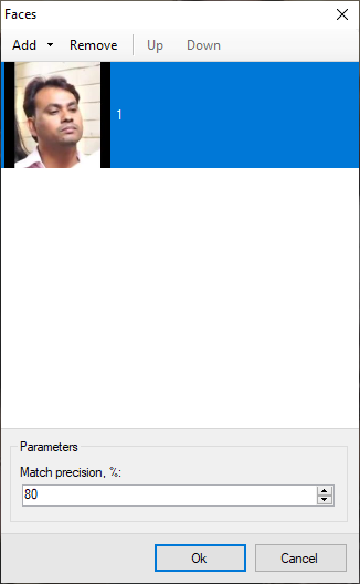
The "From clipboard" mode is convenient to use when you need to search for a person selected from the archive, viewed in a different mode or observation window. To do this, just copy the current frame from the archive and paste it into this window.

After configuring the face search parameters, click "Search" and the results will show all the detected images of the selected person's face for the specified period. The "Move analysis" button will also become available. When you click this button, you will see the analysis wizard, which allows you to compose all the moments of a person's appearance and view them in various modes – "Slide show", "Archive" or "Interactive maps". If necessary, filter the person with the button "Select faces".

«Slide show»
Allows you to start playing individual frames where a face is detected. When you right-click, you can save the frame.
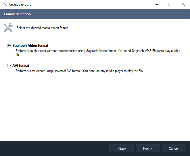
«Archive»
Allows you to view videos of a person passing in front of camera lenses and export the combined video (collected from all the videos) to a single SagitechVideo or AVI file (the "Export video"link). Videos are combined based on the time when the face is detected in the frame. Thus during the export process added a few seconds before the moment of the appearance of the face and a few seconds after its occurrence (custom settings).

«Interactive maps»
Allows you to start playing cards with a face detected on them. For this mode to work, you need to configure "Interactive maps "on the"Configuration" tab.
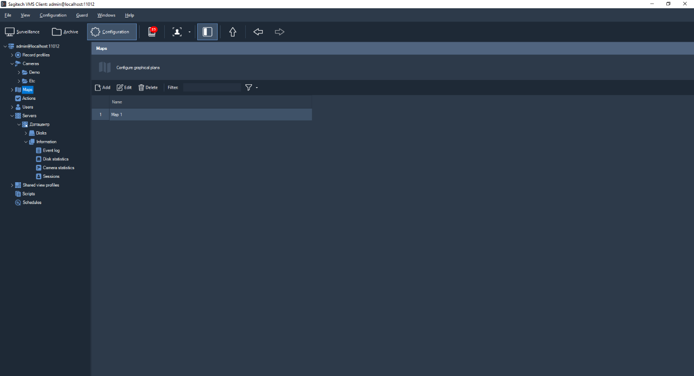
You must add a map and specify a name.

Upload a map image and add the necessary cameras. You can add cameras using the context menu in the camera tree, by double-clicking the left mouse button, or by using drag and drop. You can drag and drop cameras on an image by holding down the left mouse button. For convenience, use "Autosize".

In the move analysis mode, the map shows the trajectory of a person's movement. The camera where the surveillance object is detected is highlighted with a red frame. When you right-click, you can save the frame.

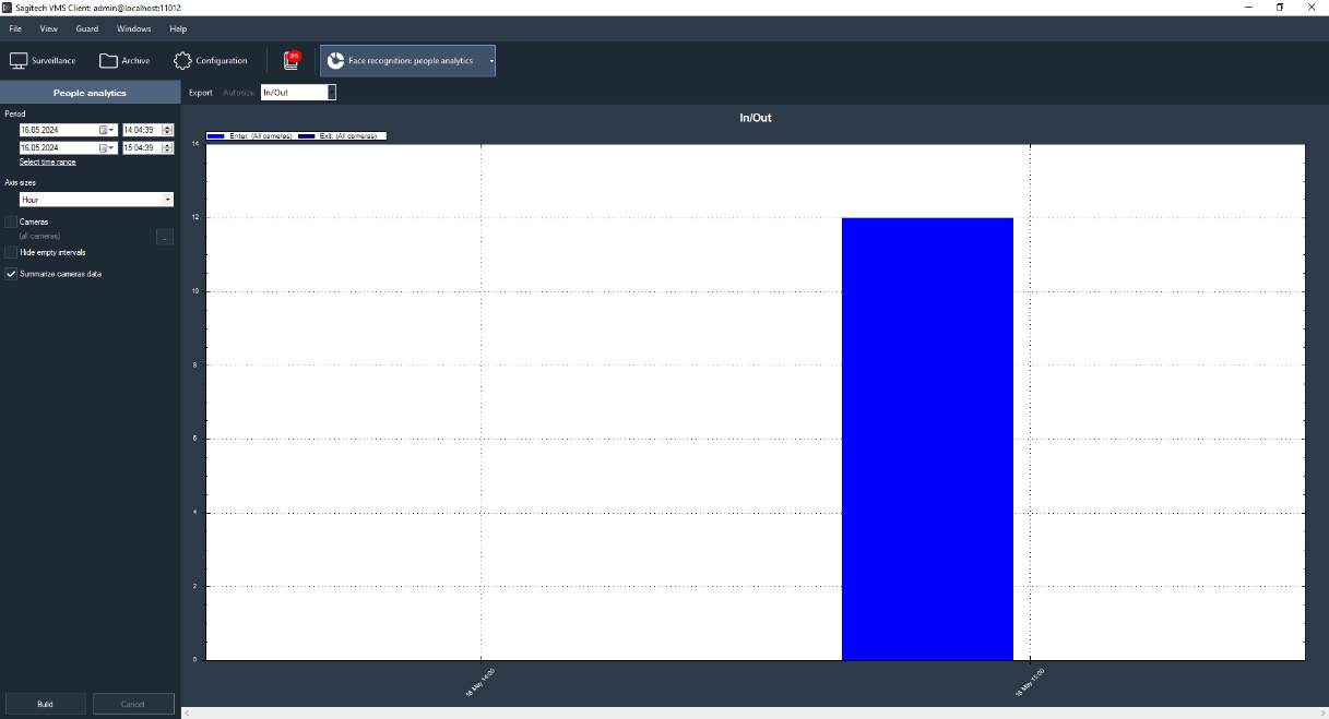
13 Face recognition module: analytics
13.1 Review
Capabilities:
-
receive and analyze data on the number of logged-in, logged-out, male, female, and unique visitors through a controlled zone over a certain period of time based on data from the facial recognition module;
-
evaluate the efficiency of the staff.
Minimum set of software tools
The module requires the following software components installed on the PC:
-
SagitechVMS (at least 1.9.8);
-
Microsoft .Net Framework 4.5 Full;
-
Microsoft Visual C++ 2015 Redistributable x86;
-
Hasp security key.
13.2 Requirements to the optical scheme
Requirements for the location of the cameras
-
Optimal camera position – the camera is aimed at the person's face;
-
The recommended horizontal deviation of the camera axis is no more than 15°;
-
The recommended vertical deviation of the camera axis is no more than 15°.
Minimum image requirements for identification
-
Recommended pupil distance is 60 pixels;
-
Minimum face size 64 x 64 pixels;
Configuring video cameras
-
The camera settings:
-
You must limit the exposure time (shutter speed, electronic shutter) or set a fixed value - from 1/100 to 1/250;
-
Adjusting the lens:
-
To configure ARD to adjust zoom and focus so that the person in the picture was not blurry and you can see the texture of the face;
-
If there is insufficient light, use additional lighting.
13.3 Parameter adjustment
To configure the module parameters, open the camera settings window, go to the "Modules" tab, and set the "Face recognition" flag.

Click the "Configure" button to display the settings window. The module is configured similarly to point (12.4). In the "Algorithm" tab, select "Analytics" in the "Mode" item.

The main modes of the module are located in the "Detection" section.
The following modes are available:
-
Detect gender and age.
-
Detect uniqueness.
-
Exit. Set this mode if the camera is pointed at the exit. In this mode, outgoing users are counted, and gender/age and uniqueness are not determined.
13.4 Interface

Data from all cameras used for user Analytics can be processed using the
specialized "Face recognition: people analytics" mode, which you can
switch to using the button  on the toolbar.

13.5 Building reports

The following parameters are available:
-
From. This parameter defines the date and time from which the calculation starts.
-
To. This parameter defines the date and time when the calculation ends.
-
Axis sizes. This parameter defines the counting interval to be specified on the X-axis.
-
Hide empty intervals. This parameter allows you not to display empty intervals before the first non-zero value and after the last one.
-
Cameras. This parameter allows you to select cameras that use the user counting module to plot graphs for multiple cameras at once.
-
Summarize cameras data. This parameter allows you to sum up the Analytics values for the selected cameras.
Capabilities:
-
Autosize. This button allows you to scale all the counter values.
-
Export. This button allows you to export graphs in .pdf format (table view) and Excel format (table + graph).
-
Report type. This drop-down list allows you to select the type of report construction: input and output, gender, and uniqueness.
14 Fisheye conversion module
14.1 Review
Functionality of the module for scanning images from FishEye cameras:
-
3 scan modes: 1x90 degrees, 2x180 degrees, 4x90 degrees;
-
Ability to control rotation angles and zoom via the virtual PTZ interface.
14.2 The inclusion of a module
To enable the module, you must perform the following steps:
-
Start SagitechVMS Client;
-
Go to «Configuration» tab;
-
Choose «Cameras»;
-
In the "Cameras" section, select the desired camera and click «Edit»;
-
In the camera settings window that opens, go to the «Modules» tab;
-
Enable and configure the Fisheye conversion module.

14.3 Configuring the module
In the settings of the FishEye conversion module, the "Parameters" tab is located. In the "Parameters" you can configure the image radius and pause the video stream.

14.4 Surveillance mode
In this mode, perform a right mouse click on the selected cell and select the appropriate mode option.

The image shows an example of a 4x90 degree conversion.
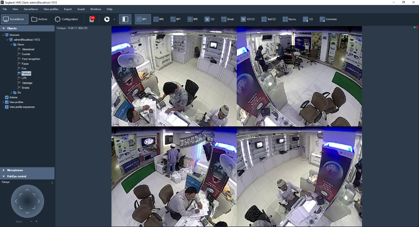
In the lower left corner, you can control the rotation angles and zoom via the virtual PTZ interface.

15 Tracking module
15.1 Review
Capabilities:
-
Determining whether an object crosses a given line, enters a zone, or stays in a controlled zone for a long time;
-
Display of objects, their trajectories and alarm lines/zones in viewing mode;
-
Ability to generate alarm events with user-defined parameters;
-
Search for disturbing events in the archive.
15.2 The inclusion of a module
-
Start SagitechVMS Client;
-
Go to «Configuration» tab;
-
Choose «Cameras»;
-
In the "Cameras" section, select the desired camera and click «Edit»;
-
In the camera settings window that opens, go to the «Modules» tab;
-
Enable and configure the Moving object tracker.

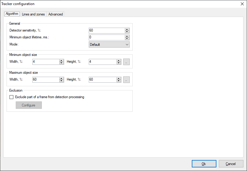
15.3 Configuring the module
In the settings of the tracking module for moving objects there are 3 tabs "Algorithm", "Lines and zones", "Advanced".
15.3.1 Algorithm
These parameters allow you to adjust the sensitivity of the detector, the minimum and maximum size of the detected object.
-
Detector sensitivity. The higher the value of this parameter, the more accurate the detection of a moving object will be.
-
Minimum object size. Allows you to set the minimum allowed size of the detected object.
-
Maximum object size. Allows you to set the maximum allowed size of the detected object.
15.3.2 Lines and zones
These parameters allow you to add intersection lines and traffic zones.
- Lines.
The user can add a line using the "Add" button.
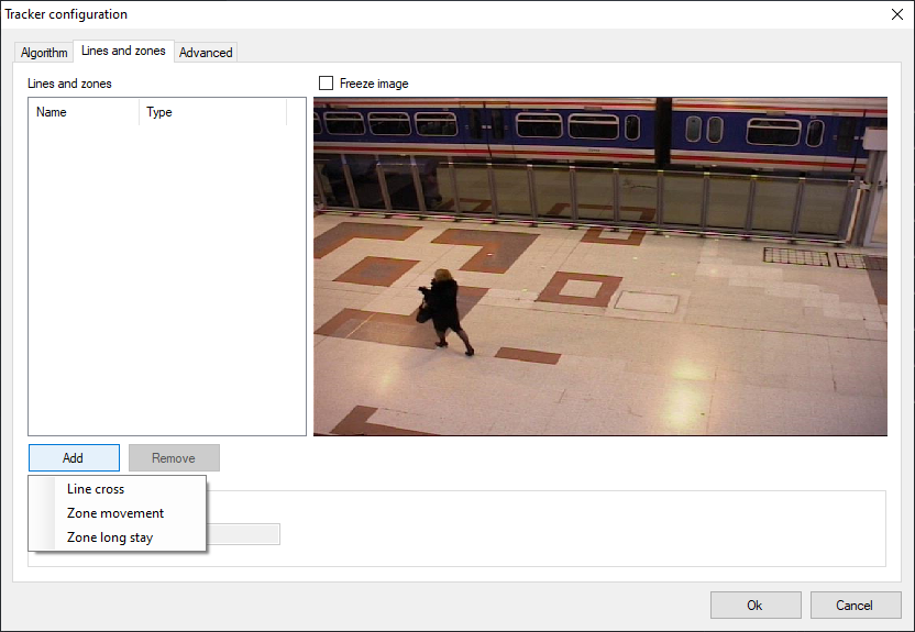
Set the tracked direction of the line intersection using the "Direction" selector.
To change the position of the line, just pull the beginning or end of the line by holding the left mouse button.

- Zones.
The user can add a zone using the "Add" button.
The image shows the default zone.
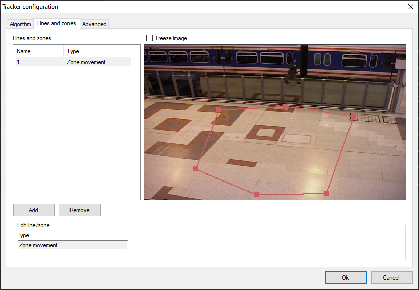
If you click on the edge of the zone with the left mouse button, an additional point is added in the form of a filled rectangle. The user can configure the zone individually by dragging these points.
15.3.3 Advanced
These parameters allow you to set automatic alarm generation and the minimum time between repetitions.

15.4 Surveillance
In observation mode, lines and traffic zones are highlighted in red if a moving object intersects them.

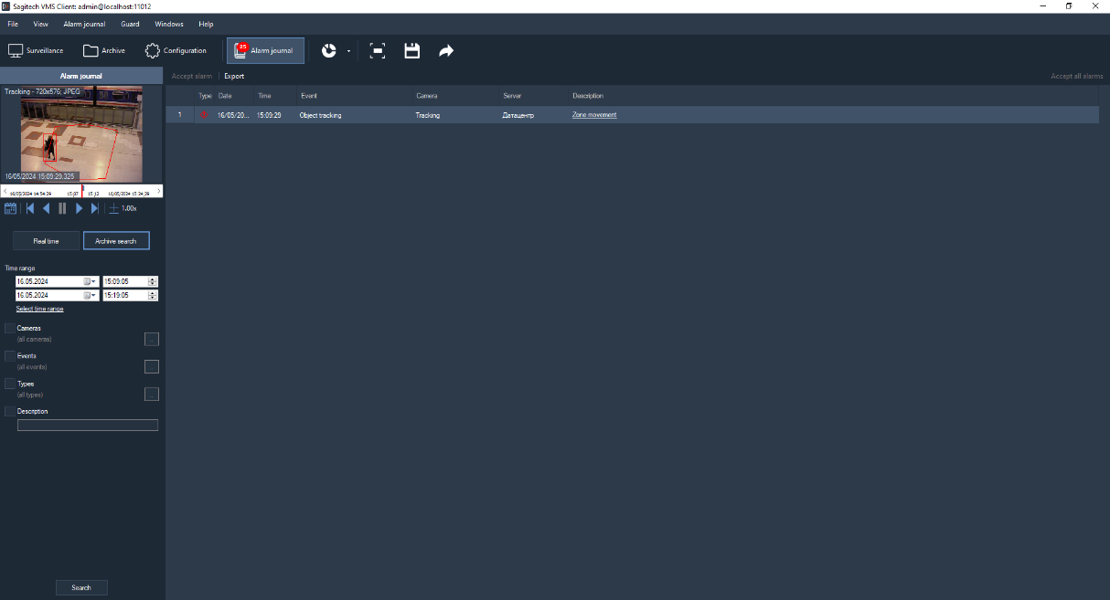
15.5 Archive search
To view the list of alarm situations that occurred during a certain time
interval, you need to use the search function in the archive. To perform
the search, switch to the same mode by selecting the menu item "View -
> search in the archive", or use the icon  on the toolbar. Quick switch
search mode on a particular camera is possible from the surveillance
mode and the view mode of the archive.
on the toolbar. Quick switch
search mode on a particular camera is possible from the surveillance
mode and the view mode of the archive.
The list of alarms of the specified type will be displayed in the right part of the search window.
16 Interactive control for Speed Dome cameras
16.1 Review
An intelligent software module allows interaction between the survey and PTZ cameras for automatic control of high-speed rotary cameras.
16.2 Module activation
To activate the module, follow these steps:
-
Start SagitechVMS Client;
-
Go to «Configuration» tab;
-
Choose «Cameras»;
-
In the "Cameras" section, select the desired camera and click «Edit»;
-
In the camera settings window that opens, go to the «Modules» tab;
-
Enable and configure the InteractiveDome module.
Note
If this module is not included in the list of available modules, it means that the corresponding license is not available on the server.
16.3 Configuring the module
Open the InteractiveDome module settings, and the following window will appear on the screen.
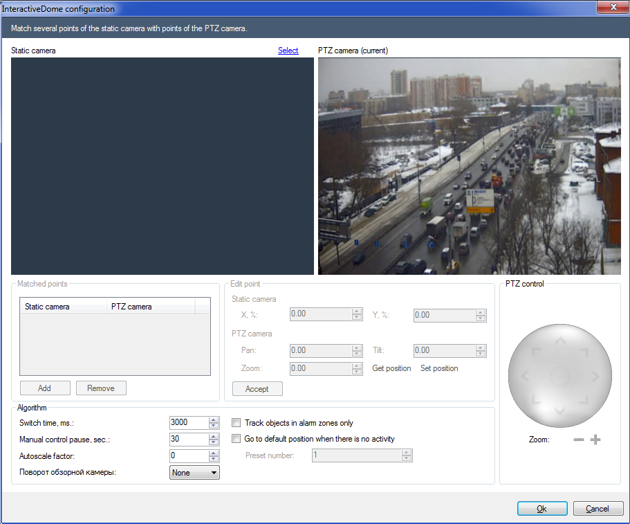
Select an overview camera using the "Select" link.
Now you need to match several points of the review camera with the same points of a PTZ camera. To add a point, click the "Add" button.

You need to point the PTZ camera at each point of the viewing camera, setting the desired Zoom at this point. When pointing the crosshair "sight" in the center of the frame of the PTZ camera should look at the point selected on the frame of the stationary camera, the size of the "sight" should approximately correspond to the size of the person at this point.
If the camera supports returning the current coordinates to the SOFTWARE, the "Rotate", "Tilt", and "Zoom" fields will be filled in any time the camera moves. If this does not happen, you will have to fill in these fields manually, i.e. enter numeric values in the fields and click the "Go" button to adjust the position of the "sight".
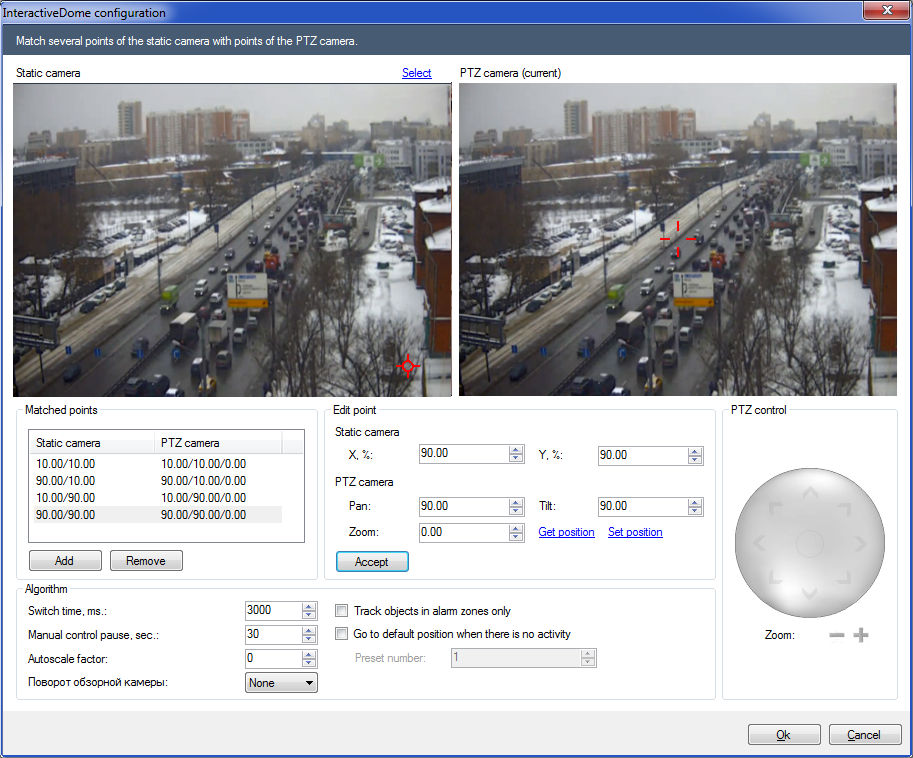
The minimum number of points to match is 4. You can add more points to improve accuracy. It is recommended to set up matching for points along the borders of the frame of the viewing camera, as well as several arbitrary points.
You can check whether the positioning settings are correct by right-clicking the area in the image of the stationary camera that you want to point the PTZ camera at. In this case, the PTZ camera should be centered on the specified zone, and the zone should be fully visible. If the hover is inaccurate, you must calibrate the point mapping by adding the center of the zone to the mapping list, if necessary. If the zoom is insufficient or excessive, then you need to calibrate the Zoom parameter for the two nearest vertical points (one at the top and the other at the bottom), or add this point to the mapping list with the desired zoom.

To enable automatic PTZ camera control, you must enable the "Moving object tracker" module in the overview camera settings.

16.4 Surveillance
It is also possible to center the PTZ camera from the "Watch" mode. To do this you need to draw the zone using the left mouse button on the image of the viewing camera.
To enable automatic centering, you must enable the "Enable automatic mode" flag in the "InteractiveDome" submenu in the context menu of a cell with a PTZ camera in "Surveillance" mode.
Important! This mode is disabled when you manually control the camera.
17 POS module
17.1 Review
The POS module is designed to monitor the actions of cashiers during the sale of goods and the calculation of buyers, as well as to resolve and prevent situations that can cause material damage to both the trading company and its customers.
17.2 Requirements to the optical scheme
A video camera is mounted next to each cash terminal. The camera lens should be pointed at the cash register.
17.3 Setting up communication of POS systems with Sagitech VMS
Setting up communication of POS systems with Sagitech VMS over the JSON protocol.
On the external system side, configure sending a request to the Sagitech VMS web server as follows.
Server address:
http://localhost:11012/rsapi/modules/pos/processreceipt?user=\[username\]&password=\[pass]

Parameters:

[username] – username of Sagitech user

[pass] - password
Request format with an example:
POST

JSON:

{

"receipt": {

"posterminalid": "2cc6ecc9-52c0-4b97-a007-2e5e8bd80c30",

"id": "2cc6ecc9-52c0-4b97-a007-2e5e8bd80c30",

"number": "123001",

"time": "2022-01-11T12:30:05",

"workplaceid": "1",

"userid": "1234",

"username": "Kate",

"items": \[

{

"item": {

"name": "Product 1",

"code": "667177655",

"count": "6",

"price": "2257.51",

"amount": "13545.06"

}

},

{

"item": {

"name": "Product 2",

"code": "875677007",

"count": "7",

"price": "3415.41",

"amount": "23907.87"

}

}

\],

"sum": "73789.23",

"paymenttype": "non-cash",

"receipttype": "sale",

}

}

Parameters:
"posterminalid" - a mandatory parameter, the ID of the cash terminal for the communication of the Sagitech VMS cash register object with the real cash register. Type of guid. (see screenshot above)
"id" – an optional parameter, the ID of the receipt. The type of guid.
"number" – optional parameter, receipt number. Type string.
"workplaceid" - required parameter, "Workplace". Connects a real cash terminal from an external system with a cash register object in the VMS. Type int. (see the screenshot above)
"userid"- optional parameter, "Operator code". The int type.
"username"- optional parameter, "Username". The string type.
"paymenttype" - optional parameter, "Payment type". The string type. The values are "cash", "non-cash", "combined". Cash, non-cash and combined payments, respectively.
"receipttype"- optional parameter, "Receipt type". The string type. The values are "sale", "refund". Sale and refund, respectively.
"code" - optional parameter, "Product code". The string type.
17.4 Parameter adjustment
To configure the module parameters, open the camera settings window, go to the Modules tab and set the POS module flag.
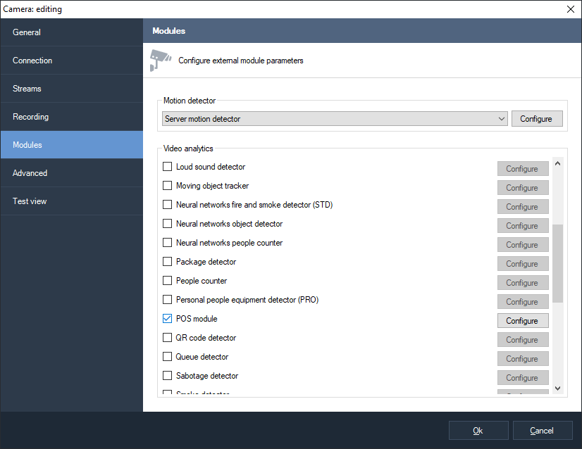
Click the "Configure" button to display the settings window.
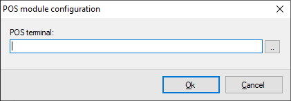
Click the ellipsis to open the terminal selection window.
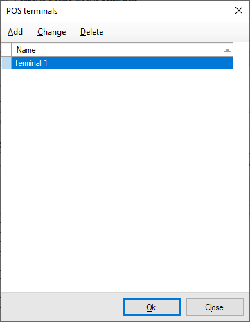
To add a cash terminal, click the "Add" button and set the parameters.

17.5 Interface
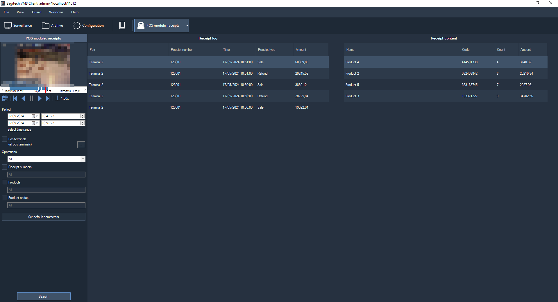
Data from all cash registers can be processed using the specialized mode
"POS module: receipts", which can be accessed using the button

This mode allows you to download the history of cash receipts from the archive of the video surveillance system. Set the parameters you are interested in and click the "Search" button.
Export allows you to save the cash transactions displayed in the log to a user-defined .csv file.
18 Heatmap
18.1 Review
The places where the movement was recorded are displayed in real time on the map in color. The map is overlaid on top of the video stream.
18.2 Configuration
To turn on the module, open the camera settings window, go to the Modules tab and set the "Heatmap" flag.
18.3 Interface
When viewing the video stream of a camera in surveillance mode, in the settings of which the "Heatmap" module is enabled, a motion map will be displayed on top of the video surveillance cell.

To build reports, use the special "Heatmap" mode, which you can switch
to using the button 

Select the time interval, the camera, and the degree of transparency of the map. You can also choose the days of the week.
And the choice of the daily time interval.
Click "Build" and a frame with a heat map will be displayed in the module interface.

By holding down the LMB, you can select an area on the map and get information about the percentage of saturation of the warm color, i.e. the degree of intensity of movements in this area.
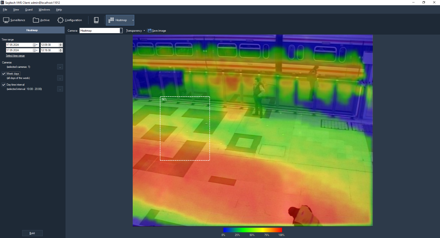
If you need to save the generated report, click on the "Save image" button. The format of the received file .jpg.

19 Neural networks object detector
19.1 Review
-
Detection of objects of specified types in the video stream - people, vehicles, animals, birds;
-
Display of objects, their trajectories and alarm lines/zones in the viewing mode;
-
The ability to generate alarm events with user-defined parameters;
-
Search for disturbing events in the archive.
19.2 Requirements for video cameras
NVidia graphics cards with CUDA 5.0 and higher, see https://en.wikipedia.org/wiki/CUDA
19.3 Installation
To start installing the product, you need to run the file SagitechNeuralNetworksSetup.exe. After initializing the installation wizard, the Installation wizard window will appear. Go through all the steps of the wizard.
 |
 |
|---|---|
 |
 |
 |
 |
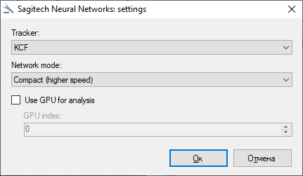
The module allows you to perform analysis on the video card and on the central processor. For faster object detection, you can enable the use of a video card for analysis. By default, the video card is not used for analysis. The module is configured using the Sagitech Neural Networks application.
 |
 |
|---|---|
After completing the installation and configuration of the module, it is necessary to restart the server part of the Sagitech VMS video surveillance system, or restart the computer.
19.4 Enabling the module
To enable the module, follow these steps:
-
launch the application Sagitech VMS Client;
-
go to the tab «Configuration»;
-
select a section «Cameras»;
-
in the "Cameras" section, select the desired camera and click the "Edit" button;
-
in the camera settings window that opens, go to the Modules tab;
-
enable and configure the "Neural Networks Object Detector" module.

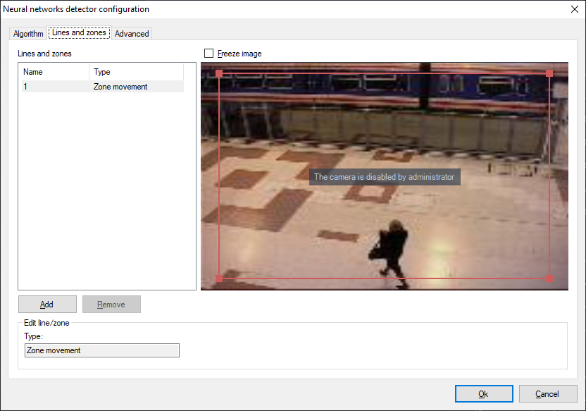
19.5 Configuration
In the settings of the neural network motion detector module, there are 3 tabs "Algorithm", "Lines and zones", "Advanced".
19.5.1 Algorithm
These parameters allow you to configure neural network parameters, video stream processing, object types and select frames that can be excluded from processing.
-
Recognition confidence threshold. The higher the value of this parameter, the more accurate the object detection will be, but the fewer objects will be detected.
-
Detrection period. To save resources, the search for objects in the frame is performed with a certain frequency.
-
Max image size. Allows you to resize the image before the analysis procedure. Recommended value – original size.
-
Track the movement of objects. It includes tracking the movement of objects between their detections, building trajectories of movement. To reduce the load, this option can be disabled if the module is used to detect the appearance of objects in the zone.
-
Object types. Allows you to recognize only selected object types.
-
Exclusion. The exception allows you to select a section of the frame that will be excluded from processing by the detector. In order to exclude frames, you need to use the left mouse button to select the desired areas of the frame, to enable detection, use the same way, use the right mouse button.


19.5.2 Lines and zones
These parameters allow you to add intersection lines and movement zones.
The user can add a line using the "Add" button.
To change the location of the zone, just drag the point by holding down the LMB.
The module interface is shown below with an example of a configured zone.
If you click on the edge of the paintwork area, an additional point will be added in the form of a filled rectangle. The user can customize the zone individually by dragging these points. Below is an example of a module interface with a configured zone.

19.5.3 Advanced
These parameters allow you to set automatic alarm generation and the minimum time between repetitions.

19.6 Setting up scripts
In the "Configuration"-"Scripts" section, you can add a script with the event type "Neural networks: object detected".

Configure the event type or object type.

And select an action for this script.
19.7 Surveillance mode
In the surveillance mode, the object is highlighted in red, the type of object and the percentage of confidence are displayed. When an object enters the control zone, or the object crosses a line, the zone/line will be highlighted.

19.8 Alarm mode
To view the list of alarm situations that occurred during a certain time
interval, you need to use the alarm log functionality. To perform the
search, you need to switch to the mode of the same name by selecting the
menu item "View -> Alarm journal", or use the icon
on the toolbar.

20 Personal people equipment detector
20.1 Review
-
Detection of objects of specified types in the video stream – helmet, surgical mask, life jacket, safety glasses, respirator, work gloves, protective shoes, overalls, headphones, helmet strap, welding helmet, safety belts, lab coat, medical gloves, protective mask;
-
Display of objects, their trajectories and alarm zones in the viewing mode;
-
The ability to generate alarm events with user-defined parameters;
-
Search for disturbing events in the archive.
20.2 System requirements
For 1 video channel:
-
CPU: Intel® Core™ i3 CPU 3.00GHz.
-
RAM: 8 GB, DDR4
-
GPU: Nvidia GTX 1050.
-
OS: x64 Windows 10.
For 2 video channels:
-
CPU: Intel® Core™ i5 CPU 3.00GHz.
-
RAM: 8 GB, DDR4
-
GPU: Nvidia GTX 1050.
-
OS: x64 Windows 10 Pro.
For 4 video channels:
-
CPU: Intel® Core™ i5, 3.0 GHz.
-
RAM: 16 GB.
-
GPU: Nvidia GTX 1050.
-
OS: x64 Windows 10 Pro.
For 8 video channels:
-
CPU: Intel® Core™ i7, 3.0 GHz.
-
RAM: 32 GB.
-
GPU: Nvidia RTX 2060 Super.
-
OS: x64 Windows 10 Pro.
For 10 video channels:
-
CPU: Intel® Core™ i7, 3.0 GHz.
-
RAM: 32 GB.
-
GPU: Nvidia RTX 2060 Super.
-
OS: x64Windows 10 Pro.
For 20 video channels:
-
CPU: Intel Core i7-10700KF.
-
RAM: 64 GB.
-
GPU: Nvidia RTX 2060 Super.
-
OS: x64 Windows 10 Pro.
For 50 video channels:
-
CPU: Intel Core i9-10940X.
-
RAM: 128 GB.
-
GPU: Nvidia RTX 2060 Super.
-
OS: x64 Windows 10 Pro.
For 100 video channels:
-
CPU: Intel Core i9-12900KF.
-
RAM: 256 GB.
-
GPU: Nvidia RTX 3080 Ti.
-
OS: x64 Windows 10 Pro.
20.3 Camera requirements
-
The sensitivity of the matrix is from 0.01 lux.
-
WDR. The function allows you to take frames at different shutter speeds and then combine them into one frame, it also helps to combat the backlighting. It is desirable to have a hardware rather than a digital WDR (DWDR).
-
FullHD format stream.
-
The focal length of the lens is selected based on the calculation of the distance of the object of analysis from the camera. The minimum size of a person in the frame, when searching for PPE, is 160*80px with a video resolution of 1920x1080px.
-
Illumination at night. The color mode allows you to effectively analyze and determine the maximum amount of information about an object in normal daylight. PPE detection is possible only in color mode without strong distortion in brightness or contrast. Switching the camera to b/w leads to a deterioration in the performance of many modules that use color as one of the main search parameters.
-
The minimum illumination of the object should not be below 30 lux.
-
H.264 video compression
-
RTSP protocol support
Recommendations for setting up cameras:
-
In the dark, turn on the color mode on the camera. The color mode allows you to effectively analyze and determine the maximum amount of information about an object in normal daylight. PPE detection is possible only in color mode without strong brightness or contrast distortion. Switching the camera to b/w leads to a deterioration in the performance of many modules that use color as one of the main search parameters. The minimum illumination of the object should not be below 50 lux.
-
Do not set low FPS or too long shutter speed, as this leads to blurring during movement and interferes with the correct operation of video analytics.
-
The image must be clear, it is necessary to avoid distortions and defects (perspective, fisheye, overlapping frames, broken pixels, etc.).
20.4 Requirements to the optical scheme
-
The recommended installation height is 2.5 – 5 m.
-
The vertical angle is not more than 60.
20.5 Types of PPE
| Name | Special requirements | Appearance | Minimum size of a person in the frame, px | Maximum recognition range*, m |
|---|---|---|---|---|
| Helmet | Color: white, orange, red, blue |
|
85х255 | 20 |
| Safety glasses | Open and closed type glasses. Restrictions for the open type: the presence of colored shackles and frames |
|
215х565 | 5 |
| Respirator | Respirator with filters |   |
170х500 | 10 |
| Reflective Vest | Color: orange, green |   |
45х150 | 40 |
| Work gloves | Color: black, gray. |    |
170х500 | 10 |
| Special jacket | Color: the main color is blue with reflective elements. |   |
85х255 | 20 |
| Work trousers and overalls | Color: the main color is blue with reflective elements. |   |
85х255 | 20 |
| Safety shoes | Work boots with lacing. Color: Black. |   |
170х500 | 10 |
| Safety harness | A strap-on safety harness with a belt and a sling attachment. Color: orange, yellow. |   |
170х500 | 15 |


* The maximum recognition range is specified taking into account the use of a 2.8 mm lens.
20.6 Image requirements
To detect people, the object must be at least 0.6% of the image size (80x160 px with a resolution of 1920x1080);
Detection of PPE – a person in a PPE should be at least 2-10%, depending on the detected PPE (150x300 - 300x600 px at a resolution of 1920x1080);
20.7 Installation
To start installing the product, you need to run the file SagitechPPESetup.exe. After initializing the installation wizard, the Installation wizard window will appear. Go through all the steps of the wizard as shown in the pictures below.
 |
 |
|---|---|
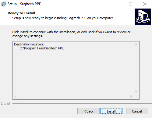 |
 |
 |
After completing the installation and configuration of the module, it is necessary to restart the server part of the SagitechVMS video surveillance system or restart the computer.
20.8 Enabling the module
To enable the module, follow these steps:
-
launch the application Sagitech VMS Client;
-
go to the tab «Configuration»;
-
select a section «Cameras»;
-
in the "Cameras" section, select the desired camera and click the "Edit" button;
-
in the camera settings window that opens, go to the Modules tab;
-
Enable and configure the module "Personal people equipment detector".

20.9 Configuration
In the settings of the module, there are 3 tabs "Algorithm ", "Control zones", "Advanced".

20.9.1 Algorithm
This tab allows you to configure neural network parameters, tracking and video stream processing.
-
Recognition confidence threshold. The higher the value of this parameter, the more accurate the object detection will be, but the fewer objects will be detected.
-
Individual recognition thresholds. This parameter allows you to set the accuracy of object detection for each type of PPE.
-
Detection zone. This area defines the area in which the PPE detection will be performed. It is recommended to limit this area by excluding non-essential parts of the frame from the analysis.
-
Object matching threshold. A parameter that displays the smoothing as a percentage. Allows you to optimize the algorithm so that it considers an object from one frame to be the same object on another frame.
-
Object recognition history length. The number of frames in which the object must be missing in order to lose it.
-
Video processing. Allows you to resize the image before the analysis procedure.

20.9.2 Control zones
These parameters allow you to add movement zones.
The user can add a zone using the "Add" button.

To change the location of the zone, just drag the point by holding down the LMB.
If you click on the edge of the paintwork area, an additional point will be added in the form of a filled rectangle. The user can customize the zone individually by dragging these points. Below is an example of a module interface with a configured zone.
In the section "PPE types amd attributes configuration" you can select the personal protective equipment you are interested in. If no type is selected, the module switches to the human detection mode in the danger zone.
20.9.3 Advanced
These parameters allow you to set automatic alarm generation and the minimum time between repetitions.

20.10 Setting up scripts
In the "Configuration"-"Scripts" section, you can add a script with the event type "Neural Networks: PPE Detection".

And select an action for this script.
20.11 Surveillance mode
In surveillance mode, the object is highlighted in red if there is no PPE and the type of PPE is displayed.
20.12 Alarm mode
To view the list of alarm situations that occurred during a certain time
interval, you need to use the alarm log functionality. To perform the
search, you need to switch to the mode of the same name by selecting the
menu item "View -> Alarm journal", or use the icon
on the toolbar.
21 Dashboards
21.1 Review
This module allows you to display data from analytics modules in graphical form.
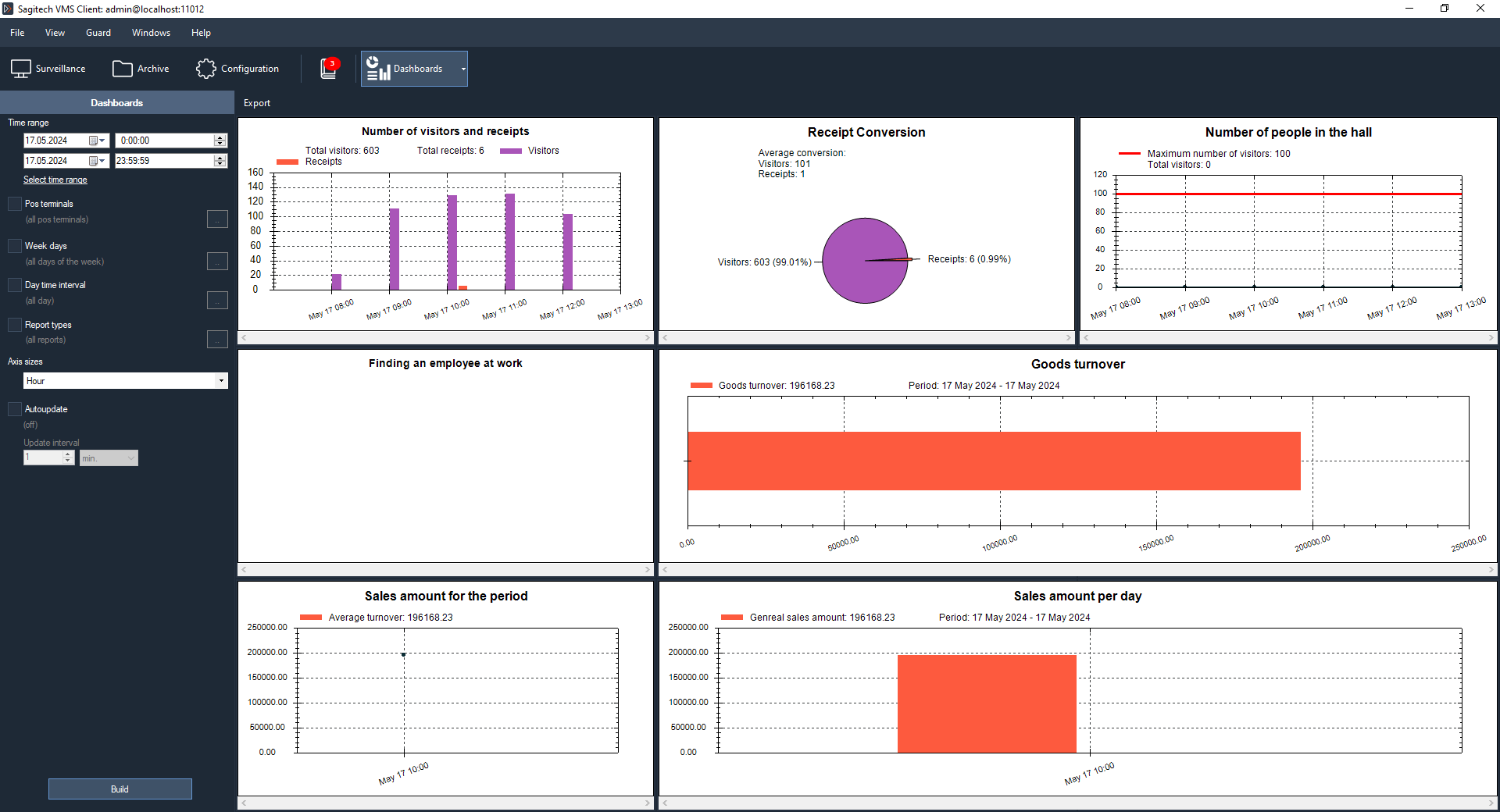
21.2 Building reports
On the left side of the interface, select the desired mode of operation and search filters.
The following filtering options are available:
-
Pos terminals
-
Week days
-
Day time interval
-
Report types
-
Axis sizes
The following types of graphs are available:
-
Number of visitors and receipts;
-
Number of people in the hall;
-
Conversion to receipt;
-
Trade turnover;
-
Total sales for the period;
-
Total sales per day;
-
Finding an employee in the workplace.
21.3 Autoupdate
By default, charting works in manual mode. You can automate the plotting. Set the "Autoupdate" flag and select the update interval. By default, the charts are updated every minute and when events are received.

21.4 Setting up notifications in Telegram
In the user settings, go to the "Advanced" tab and click the "Configure" button.

Enable integration with Telegram. Click OK.
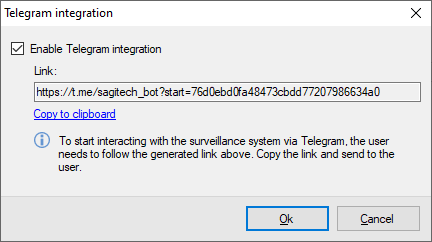
Save the changes.
Click on the generated link. And click "Start". Upon successful registration, you will see the message "You have successfully registered".
The Schedules subsection allows you to set a schedule for performing certain actions/scenarios specified by the user.
To add a schedule, click the "Add" button and enter a unique name.

In the "Conditions" tab, set the start time of the required actions, the type of repetition, etc..

In the Actions tab, select the Dashboards: Summary.
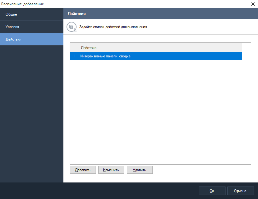
In the "Actions" tab, select the "Send message to messenger" action.

Select the user and the message text. To get a summary of dashboards, it is enough to use the %ReportSummary% parameter.
